Large utility generators always rotate under load after being first spun-up, by a pony-motor, via an overrunning clutch.
Similar clutch access to a legacy generator shaft allows kite energy to be mixed in, as a hybrid plant.
Large utility generators always rotate under load after being first spun-up, by a pony-motor, via an overrunning clutch.
Similar clutch access to a legacy generator shaft allows kite energy to be mixed in, as a hybrid plant.
And also I don’t see any strategy to assure automated takeoff and landing.
Provide a big green ISO-compliant button.
I was only looking at the shaft just now. For sure a 100 m wide carbon structure is not easy to handle. This is not a full design. Just investigating where the lead goes…
Tallak: Just investigating where the lead goes…
Airborne assembly of unit-scale-limit components will become a standard mega-scaling solution, eliminating bulk launching and landing; for vast airborne structures that never come down, only swap parts.
Really interesting to mention settling-under-power. Especially where widely spaced wing (tips) without a central shaft structure like Daisy are involved. Is that their default state?
From a personal experience, as passenger of having to avoid settling under power, when having no tail rotor pitch control once … eugh. Not a fun way to land. Well done pilot.
Yeah, that’s a huge sounding shaft.
Like I said before… not sure it needs to even be there.
Might work in that case though.
Generally yes given a huge torque like you pointed out… a generator is going to turn… Why wouldn’t it?
The interesting thing about Daisy pointed out by analysis @Ollie did …
Not only does the shaft compress with extra torque… this compression pulls the blades into wind, which increases the windspeed, amplifying the gust.
Sounds pretty scary and overly dynamic doesn’t it.
You should try one.
Indeed the power/land use ratio goes increasing. As the tether length is 400 m, the land use would be roughly 0.5 km² (400 m radius by taking account of wind changes), and for 5 MW. The land for the 216 m diameter rotor is difficult to determine as the rotor would remain tilted on its tilted 72 m diameter ring-generator.
This topic is about torque transfer systems, of which TRPT with rigid elements aloft for the compression “stars”. Now let us examine the only one TRPT with only tethers between the horizontal ground rotor and the flying rotor: the rotating reel system.
Assuming a same tether length of 400 m, the land use would be the same, so 0.5 km². Now the outer diameter of the rotor is 1.5 X 216 m, so 324 m (not more in order to respect the marge with the ground), leading to a power of 11.25 MW. The diameter of the ground rotor is about 300 m. The diameter of the tether fixations on the flying rotor is about 200 m.
The land use by the ground rotor is its area of 0.07 km². Is it too large? No, because the land use by the flying rotor when at ground is even a little more. And the ground rotor is used for takeoff and landing. There is no compression structure aloft issue, so that it can scale by ground and flying rotors scaling. So the power/space use ratio can be maximized at any scales.
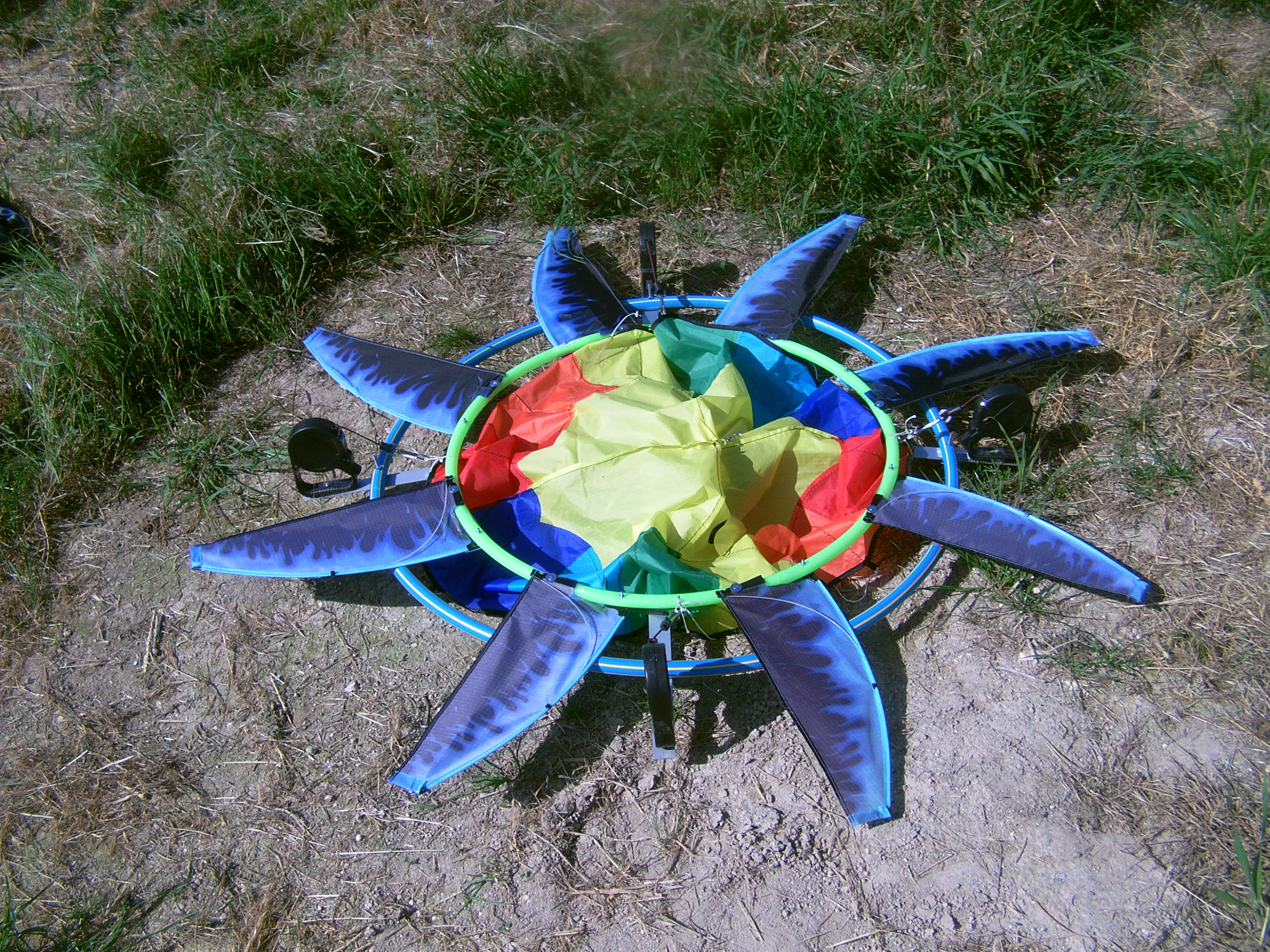
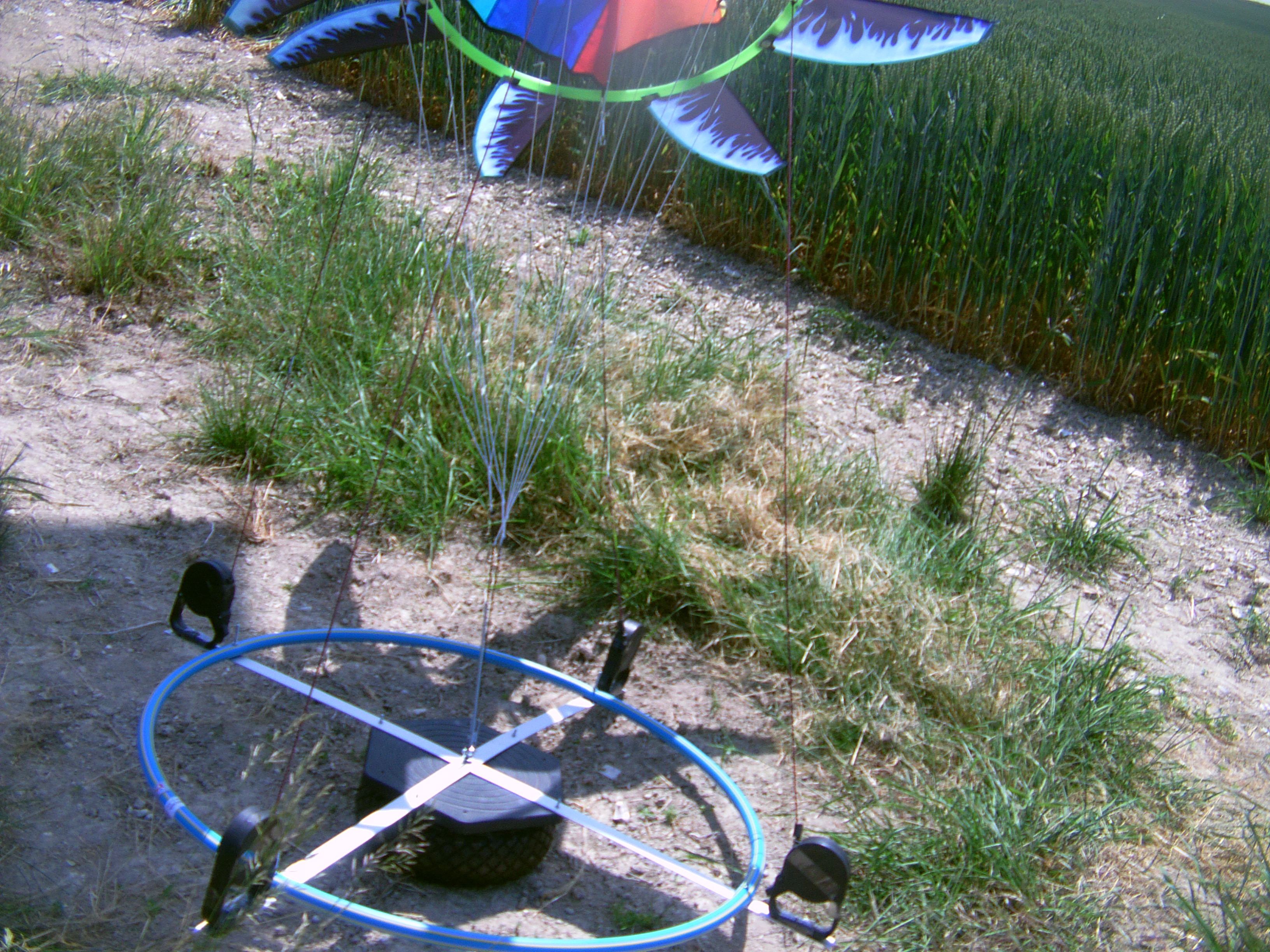
There are a lot of possibilities of rotor building, so the photos below are only examples.
https://www.researchgate.net/publication/324135034_Airborne_Wind_Energy_Conversion_Using_a_Rotating_Reel_System
Before takeoff:
In operation:
In a synchronous grid, its best to spin up a large generator unloaded and then engage load and kite power smoothly, due to hysteresis of lugging, which can break parts. Otherwise, in small stand-alone systems, spin-up unloaded generator, then engage load.
/////
Landspace is maximized relative to AWE capacity as a kitefarm becomes wider and more stack-layers of wings can be added to higher altitude, while keeping tether-scopes within farm boundaries. Topological stability of interconnections aloft (kite network) presumed.
Indeed by using the rotating reel system soft rotors could taking off by being the ones on the others and then separating into the sky to form a train of rotors while the tethers are expanding. Numerous things are possible by using a horizontal ground rotor. A big advantage of the soft wings is the low cut-in speed.
Carousel and Rotating Reel footprints leave a large hole in the middle as they grow very large. That’s a scaling limit effect.
The hole is filled by the inner area of the rotor, and yet more by implement a train of rotors as I suggest in my previous message.
Filling the hole in the middle with fabric does not add much power to a big wide ring.
Having a tall proportioned stack wastes a lot of space for its fall-down safety-zone.
A lenticular kite network formation seems to me to scale the most, for example, 10km high and 30km across, with no fall-down outside of its footprint.
I have some ideas to fill the hole, and the hole is not a serious problem for scaling, as its area is relatively low in regard to the whole area: 1/3 (example an outer diameter of 70 m and an inner diameter of 40 m) or 1/4.
The all-down safety-zone is comprised in the space and land use. So a train of kites using longer tethers use also more space as I explained numerous times. It is an affair of compromise. A short train of 2 or three kites can be implemented if we want a “smaller” ground rotor.
If problems of scaling occur only from 10 km high and 30 km across, it is not so important. A Rotating Reel system could perhaps be 2 km high (10 km by using a train of kites) and 2 km diameter, knowing huge wings should be implemented.
A “lenticular kite network formation”: it’s a bit vague as a description. Please open a new topic if it is not a torque transfer system.
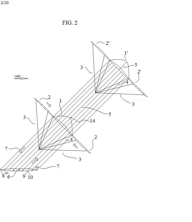
Rod and I have shared a lot of lenticular formations over the years. No need to open a new topic, as the point is only to compare against torque transfer airspace and land footprint, as presented here. The patent drawing seems to show rigid spar kites, whose spars would not scale close to km scale. Center fabric is more slow “hub area” than fast “tip only”.
The patent shows bridled wings. Rigid and soft wings can be used as well, rigid wings scaling less. The center fabric parachute (on the patent and on the photos) is not quite useful. It is a point for R&D, but not a main point. Many studies are to be done to implement a rotor. Attach 4 soft wings forming 4 blades is a beginning.
Waiting for a description of lenticular formations in an appropriate topic.
Bridled Spar Wings shown in patent drawn so straight. Big rigid kite wings need bridles.
There is also the cost of track and train cars, or huge carousel; and questions of VAWT phase efficiency. Ring architectures must prove these are worthwhile trade-offs against all other major AWES architectures. The biggest ring so far seems to be your prototype rotating-reels. It would be nice to see 10m scale testing next, with design refinement.
As a curious fact, the largest offshore VAWT “ring turbines” were the ocean triangle routes of the Golden Age of Sail. Worked rather well…
You made relevant remarks.
Yes, the figures (Fig. 2 above) on the patent (FR3034473A1 - Eolienne aeroportee rotative - Google Patents) can represent rigid as well as soft kite wings. The design of the wings is not specific to the system and to the patent which essentially deals with the conversion system. Much work can be made for the rotors due to various possibilities. I indicate above a first possibility with four spaced wings in opposition.
Indeed I have a poor prototype of about 1 m. As I am alone and have limited possibilities unfortunately I cannot do more. Indeed a 10 m scale testing next would be great but could be only assured by a (even limited) team assuring all the components comprising the automated management, and by using a permanent experimental site. I am far to have this.
Even @Massimo has not built any carousel, explaining that a large minimal rig (more than 100 m diameter for the ground ring if I am right) was required, due at least to the configuration with kites flying by figure-eight while the ground ring rotates by relatively low speed. I do not have as much size requirements for the rotating reel system testing, far from it.
https://www.researchgate.net/publication/324135034_Airborne_Wind_Energy_Conversion_Using_a_Rotating_Reel_System is a very precise and complete simulation and mentions also some balancing issues that can occur then be corrected. But a rig with only one rotor has be studied. As the height reached with a 10 m diameter ring would be only 10 m in order to benefit from a maximal torque transfer and a minimal size of the lifting kite if it is required, a train of kites could also be studied. But I think the control (comprising takeoff and landing) of a single rotor would be easier, at least as a beginning.
A preliminary remark: the altitude reached by the kites of the KiteGen or NTS carousels or reached by the rotor of the Rotating Reel System are the same in regard to the diameter of the ground ring.
The ground ring should not be raised with poles because it would undergo too heavy loads and should be expensive. I rather see a cable or a rail at ground level and a fence surrounding the whole and
with openings for maintenance and secondary uses like agriculture and, as for all AWES architectures, delimiting the footprint which not be confused with the land and space use which is far larger. A big advantage of carousels or rotating devices is a continuous power.
Other AWES architectures are reeling (yoyo) with their intermittent working being able to cause expected rapid damage for the mechanical parts as well as the generator. And the scalability of a winch is not obvious due to the low reel-in speed.
The figure 5 of Payne’s patent (US3987987A - Self-erecting windmill - Google Patents) represents two rigs. As they are connected with a long bar to face the wind, the whole can be as expensive as the carousel, and the efficiency of this transmission has also to be proved.
Now flygens can be a possibility, but a tethered multi-rotor (MAWES) works only by a computerized management (as for yoyo MAWES). If it fails, it is the end of the story.
USP3987987fig5 does not use a “long bar to face the wind”, but the ground itself as an anchor medium. kFarm showed that crosswind anchors are cheap and simple to use. The trade-off to this minimal capital cost option is belay between anchor points, to maintain crosswind motion. To anyone not familiar with ordinary industrial rigging belay practice, the cost of large rotating structures may seem necessary.
Crane-work, ship-mooring, train-connects- All are cheap industrial belay cases. There is also tri-anchor tri-tether rigging, with no belay, for crosswind motion supported in any direction. And trade and gap winds can be essentially one direction, without rotation need, like Curacao, for example.
Without a “long bar to face the wind”, USP3987987fig5 cannot face wind changes. To anyone not familiar with ordinary features of the wind, wind energy may seem a mystery.
There is nothing about capabilities of tri-anchor tri-tether, no calculation, no scientific paper.