You seem not to recognize belay-around-an-anchor-circle as a AWES method. There really is no long bar in the patent (much less any long bar “calculation” or “scientific paper”).
On the other hand, there is both experimental (KiteLab) and formal (TU Kaiserslautern) tri-anchor tri-tether work not to be overlooked-
The scientific paper does not refer to KiteLab’s work which should be referenced, and also does not inform how the tri-tether installation can scale or generate more power.
Moreover the tether between the three rigs make a big obstacle.
TUK was unaware of KiteLab’s prior work when they published, but since then we have exchanged many nice emails on shared AWES concepts. Be patient in how this research unfolds to meet your criteria for acceptability.
The tri-tether method actually helps constrain the kite to a tighter pattern scope than a single-line can, and better retains the kite inside the land footprint, with far less chance of breakaway, than single-line topology.
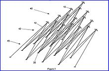
Our oldest variable tri-tether aviation case is a 1930’s Zeppelin patent, at a grand scale. Tigner’s patent shows tri-tether array scaling.
Form a new topic if this discussion is not enough.
In scaling a rotary tether power transmission system, one thing to be particularly wary of is tether drag.
Especially if you use a stacked system where lower tethers with higher tension are thicker.
For the same rotor size and speed, you can significantly reduce tether drag by using smaller diameter shafts at the lower end.
Given a high enough lift wing set, you could run torque down something completely soft like the web of enforcement webbing seen in one of these…
Such a PTO geometry minimizes angular velocity, such that a more massive hub mechanism and higher step-up transmission is needed to match rotation to a large generator.
Yes, the linear velocity, of a point on the smaller diameter part of a conic TRPT cone web is reduced, the torque is the same, meaning higher relative turning force compared to lifting force e.g. more twist & torsional compression on the lines for a smaller diameter. It is harder to resist twisting using a smaller diameter…agreed.
This torque at small diameter is easily fed into a gearbox, The hub is a lot smaller than a large ground ring track, The generator can now be stationary without needing to run around or be driven by a large track.
The saving of land area with a smaller diameter of the lower part is an illusion, because the rotor on the ground will take at least the same land area.
The diameter of the ground horizontal ring of the rotating reel system can be relatively reduced by implementing a train of rotors. The ground rotor should have roughly the same diameter as the flying rotor(s) to facilitate takeoff and landing.
Every turn of a “rotating ring” system where the ground plane ring is misaligned with the rotor plane ring, requires the perimeter lines to cycle in and out over a winch drum (or matched central pulley set equivalent) with at least the full torque load, even when using a central anchor line to a star bridle to support against lift in the rotor.
How does that scale in time?
In spite of the misalignment the electrical winches are controlled in such a way that “the tension in the tethers is equal and constant during operation” as specified (see the quote from the chapter 22 below). So after what the tilted position of the flying rotor is assured with the same means as for another rotating kite, more the bridle tilt support which is not useful (see just after).
The details with the advantages and disadvantages of the central anchor line to a star bridle are indicated in the chapter 22, text and Fig. 25.5 a) full tilt support; b) strong tilt support; c) no tilt support. I think only the central rope
( c ) should be kept, but it should not be stretched to avoid drawing off power. So the tilted rotor is kept in position by a lifting kite or/and within a train of rotors or/and by aerodynamic means by using a cyclic active control of the blades-wings I envisage.
Scaling is not a problem if the proportions between the ground and the flying rotors are respected. The figure 22.18 and the explains show that the ground and the flying rotors should be close each other in order to maximize the torque transfer to obtain the value of 1 (which is the maximal transfer value, with no loss, that with minimal axial force before being completed with more axial force) if the axial force is not completed by a lifting kite or similar. After that it is possible to add a train of rotors since the transfer torque would be made in regard to the first rotor, all rotors being aligned each other.
As a consequence a train of rotors would generate far more axial force, allowing the first rotor to be farer from the ground ring by keeping the maximal transfer value to the ground ring.
On the paper that works, some issues (balancing) being likely able be solved. In spite of my too small prototype of 1 m, the ring rotates while the lines vary. With a 5 m or 10 m prototype the adjustments could be made.
I think if you scaled a horizontal ring on ground with a elevated TRPT, using pulleys like Pierre’s patent, you would probably have some issues with heating in the tether along with rapid wear. My guess is the solution to this might be something based on chains or even something completely different (electrically coupled winches?). It may not be impossible but the really straightforward way of tether and pulley is not a good way, I think.
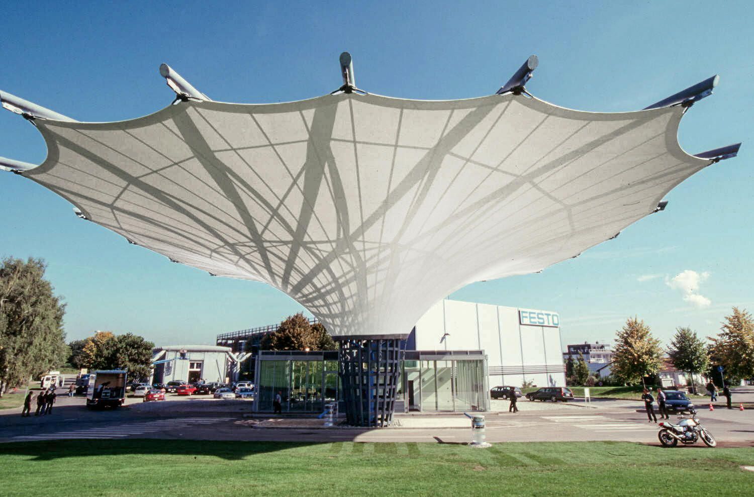
Oh: if the TRPT is elevated 30 degrees, and the receiving end is a kind of large ring, the ring will be angled 60 deg to the ground, and if you place the ring on a small tower, the ground use will be very small (expecting eg farming is possible beneath the ring)
There is no pulleys in my patent. The idea of pulleys came after. On my patent I mentioned winches with springs, then electric winches automatically managed as second embodiment.
Initial ideas perhaps were better, excepted for the winches with springs that do not allow an equal and constant tension in the (peripheral) tethers during operation.
It is the described solution on the chapter 22. And electrical winches can be “controlled in such a way that the tension in the tethers is equal and constant during operation”. I think this could perhaps be the only one mean to assure an equal and constant tension in the tethers. Using pulleys as a passive mean for the same could be less accurate (beside it the wear is not a major concern as a cable could be used imho).
But when the flying rotor is on the ground (and how when the basis is tilted? By using an articulated tower in order to get the ring horizontal as the rotor is at ground? It would be too fragile given the enormous forces from the flying rotor), the used land area is yet larger than the horizontal ground ring area. And farming can be possible inside the ground horizontal ring.
The horizontal ring also facilitates takeoff and landing whatever the wind direction.
Tethers alone for the TRPT looks to be a simple and efficient way even as numerous issues must be solved, by testing a prototype of about 5 m diameter. The result is not guaranteed but it is worth a try. Other solutions are limited imho.
“22.3.2 Direct Mode of Energy Generation
In this mode the rotational motion of the ground rotor is converted directly into
electricity, using one or more generators that are coupled to the rotor by a gear
mechanism, as illustrated schematically in Fig. 22.1. The winch modules manage
the kinematically induced length variation of the peripheral tethers, as shown in
Fig. 22.4. They are controlled in such a way that the tension in the tethers is equal
and constant during operation. The modules are electrically interconnected such
that the generated and consumed energy is balanced, avoiding the implementation of
expensive temporary energy storage. To account for losses in the electrical machines
a small amount of electricity is provided by the main generator which is driven
directly by the rotor.
By adding suspension lines, as shown in Fig. 22.5, the force level in the system
of peripheral tethers is lowered and, as consequence, also the generated and consumed
amounts of energy. Because of the reduced losses in the electrical machines
the total amount of electrical energy required for the actuation of the tether system
is decreased. However, with the addition of suspension lines the tensile torque
transmission system becomes more complex and in particular also statically indeterminate
(hyperstatic). As consequence this poses additional challenges to the control
systems of the winch modules.”
I would add that the suspension lines reduce the axial force, so the torque transfer value.
I just built then experimented a rotating reel system comprising a ground ring with ropes and pulleys, rotating a superior ring with my hands. The conclusion is clear: when the two rings are aligned and parallel (not rotating reel) the rotation is far easier than when the superior ring is tilted, involving ropes sliding in the pulleys forth and back (rotating reel). It becomes yet more difficult when the superior ring is both tilted and distant, as expected with the figure 22.18. In the other hand my pulley system is not multi directional, so their cyclical adaptation to the angle of their respective tethers is not assured. So significant frictions occur. However I will provide a possible explain in the dedicated topic. However other (and this time simpler) methods avoiding a compression structure can perhaps be possible.
However the chapter 22 mentions in the page 566: “This essentially means that the transmission efficiency for the ideal system in steady-state operation is, as expected, 100%.” and in the ages 564 and 565: “The solution is approximative because the residual transverse forces are causing compensating motions which are not taken into account in the analysis. However, the following results indicate that the effect of the compensating motions is minor and can be neglected.”
A 100% transmission efficiency is theoretically possible. But the physical model is not respected by using leashes (different forces during winding and unwinding) or by using pulleys (forces theoretically equal and constant if the pulleys are well oriented during the operation, but it is not the case). There are also frictions.
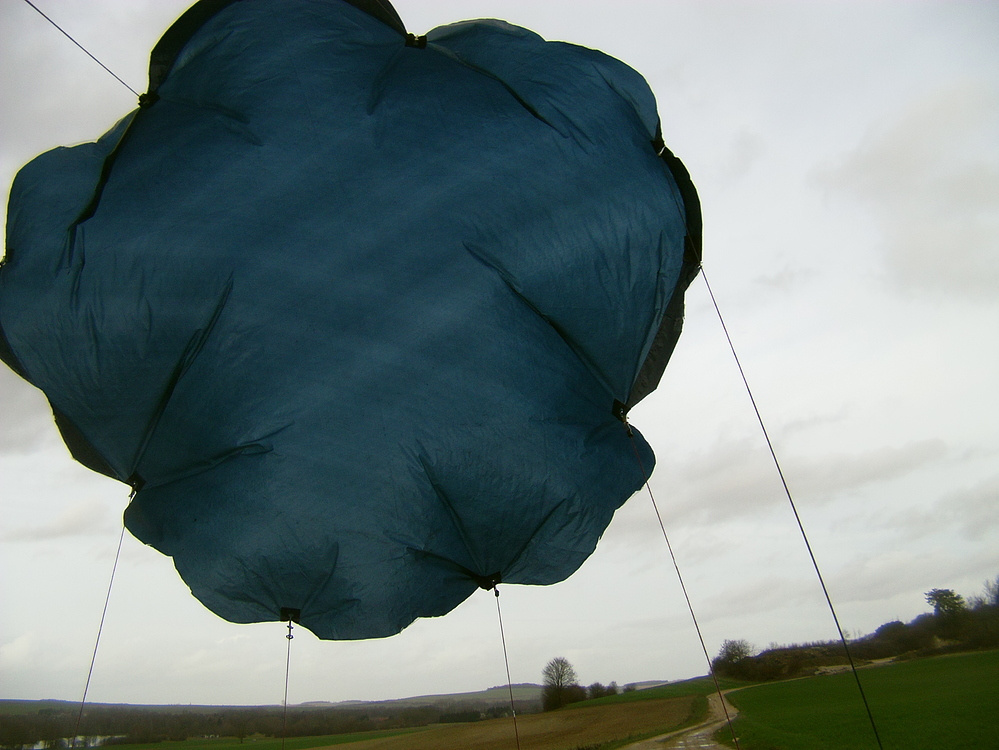
The perimeter of a Network Kite Turbine rotor is generally in tension when it flies as an autogyro,
It’s large tensile flying form is maintained with wind pressure. That means it can scale.
To get it in place flying and back again however requires some rigidity. Rigidity doesn’t scale well.
Interesting to consider how we might change scales of rotary systems.
What kind of mech & tech mixes can we use to exploit the best of both modes?
This topic thread is medium scale TRPT but I’m always interested to consider the limits…
A limit in the potential to scale a TRPT (Tensile Rotary Power Transmission) will be how you implement the PTO (Power Take Off) mechanisms.
A TRPT comes to the ground with an elevation angle and spins transmitting torque.
A PTO holds the tethers at the end of the TRPT and extracts power by applying braking force to TRPT rotation.
You can have
a PTO where the axis is Aligned to the TRPT axis - like Daisy Kite turbine
(needs alignment tech)
or
a PTO on the ground with a vertical axis holding a TRPT - like Rotating Reel System
(needs cyclic tether length adjustment tech)
A larger ring PTO means easier torque transfer but a much heavier and more flexible machine.
A ground based PTO ring system intuitively seem easiest to scale - e.g. was Kitegen carousel ring ~1km proposed diameter? >1GW output. The design was like TRPT - a continuous rotary track. Multiple kite control pods running around the track. The output was basically proposed to be braked rotation.
Scaling a Tilting a wheel PTO is intuitively hard. How do you support and brake a large tilted rotating device above the ground? (without using a big tower again. ) and at scale?
Something like a Stuart Platform Hexapod
or the Daisy ground stations would be hard to scale >30m
(Would it ever even need to scale beyond that size is another question which could be mitigated with high tension lines, high L/D kite stacking )
Rigid systems scale and move better on water so
Potentially a PTO offshore where the tension pulls a buoy PTO over for alignment might work at scale
Like in this very old (embarrassing) drawing
or
to stay above land using a tensile rim support might alleviate the problems of scale…
This tensile rim support would still need active line management for wind alignment. But that has a much lower duty cycle than cyclic line length re-alignment where line length is altered continuously with each shaft rotation.
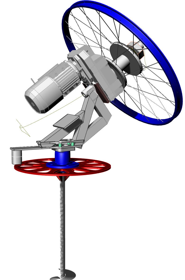
A variant of the last drawing: a swiveling horizontal ring is implemented on the big poles or directly on the ground, in order to allow the whole installation (comprising the generator and the tilted ring for PTO) facing wind direction.
In another variant, one or more poles are the generator(s), the inclined ring is removed: this becomes a rotating reel system. It could be a plan B if, at each revolution, it was possible to compensate for the jolts by suitably oriented deformations of the flexible rotor.
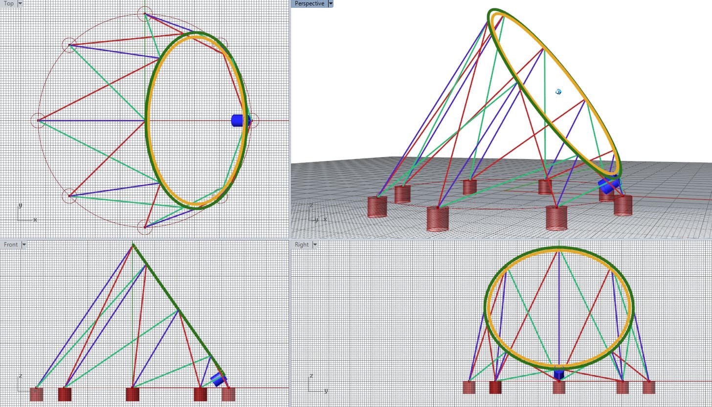
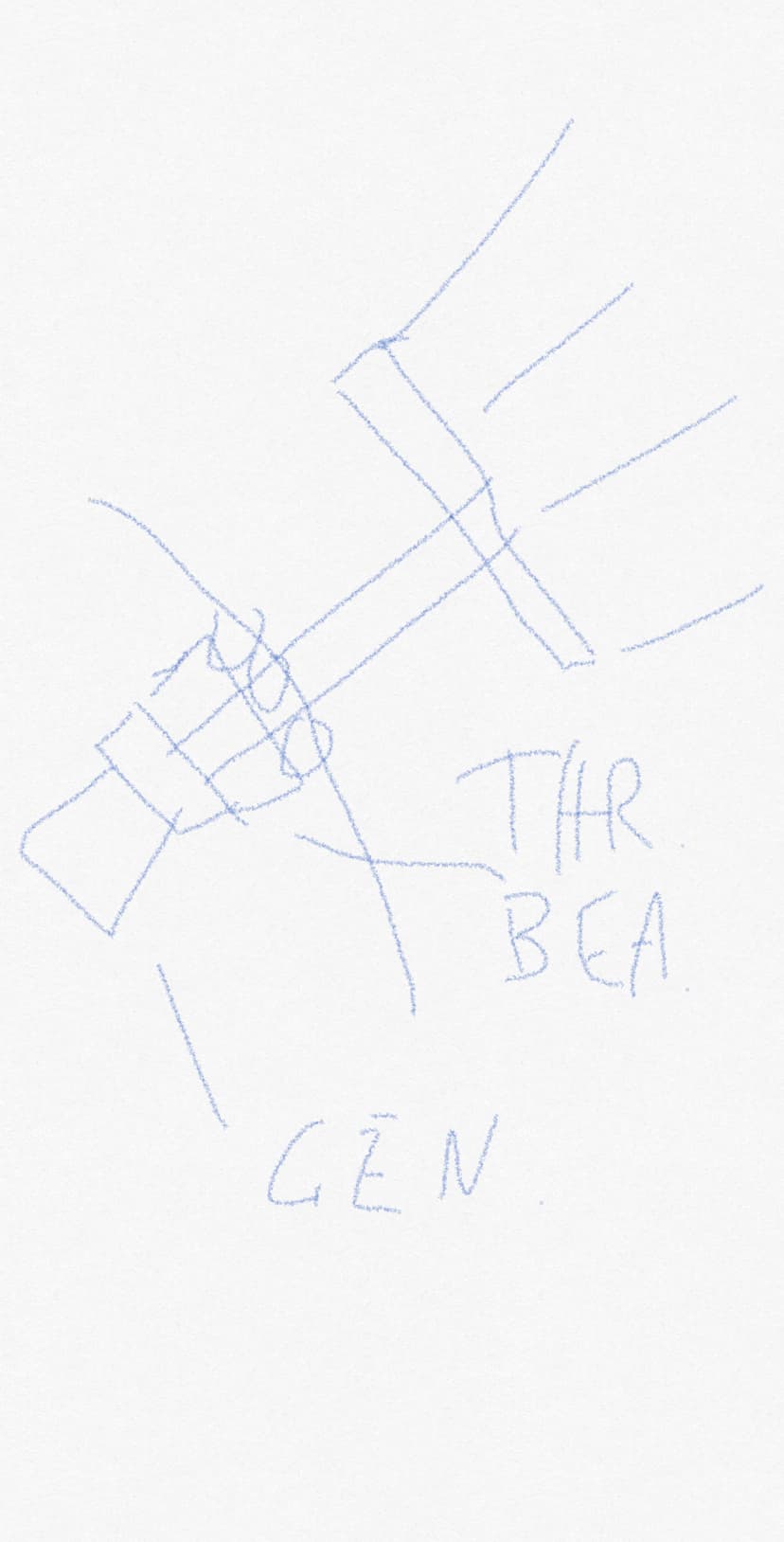
I think this is a reasonable approach. The PTO is connected to a shaft that rotated in azimuth and elevation. The generator is connected to said shaft.
A thrust bearing (and other smaller ball bearings) support the shaft and prevent it from being pulled out of its socket. The thrust socket is the point that takes all the lift of any kites, a substantial force.
Azimuth and elevation must be aligned at a rotational center which should be the same point. Also the shaft should go through this point.
Careful balancing of mass allows the mechanism to rotate quite freely in elevation.
A flexible cable connects the generator to the base. If the windmill does not need to rotate 360 degrees, no slip ring is necessary.