Hi @PierreB
There were no poles in the tilted ring drawing
The two tilted rings are a solid track generator ring rail (green) and a rotating PTO hoop (yellow)
The rest of the crossed conic lines(r,g,& b) are tie supports (active line tesnion) to support the rim and prevent further torque transmission…
If it wasn’t clear - I should clarify that on the post
It sounds kinda like the plan but
need a bit of a gear up powertrain before slapping a generator on the back
also need to control the El and Az with a drive… Because If the whole thing is free to follow the tension… and the kite starts moving, as it will, You can get the mass of the ground station into a swinging, which at low frequency can feed back into the resonant frequencies of the whole system. and mangling the transmission. I have found too many ways of doing that already.
The sticks in the back here are to stop swinging
I see sorts of big red poles, eight in number. Is it something else?
Because the tension is so high, some oil dampeners may be enough to cancel any oscillations. For a prototype an electrical drive is probably ok, but I would have preferred something non-powered if possible.
1 Like
Apologies, yes @PierreB
those red cylinders were there to represent anchor and underground level line handling systems
1 Like
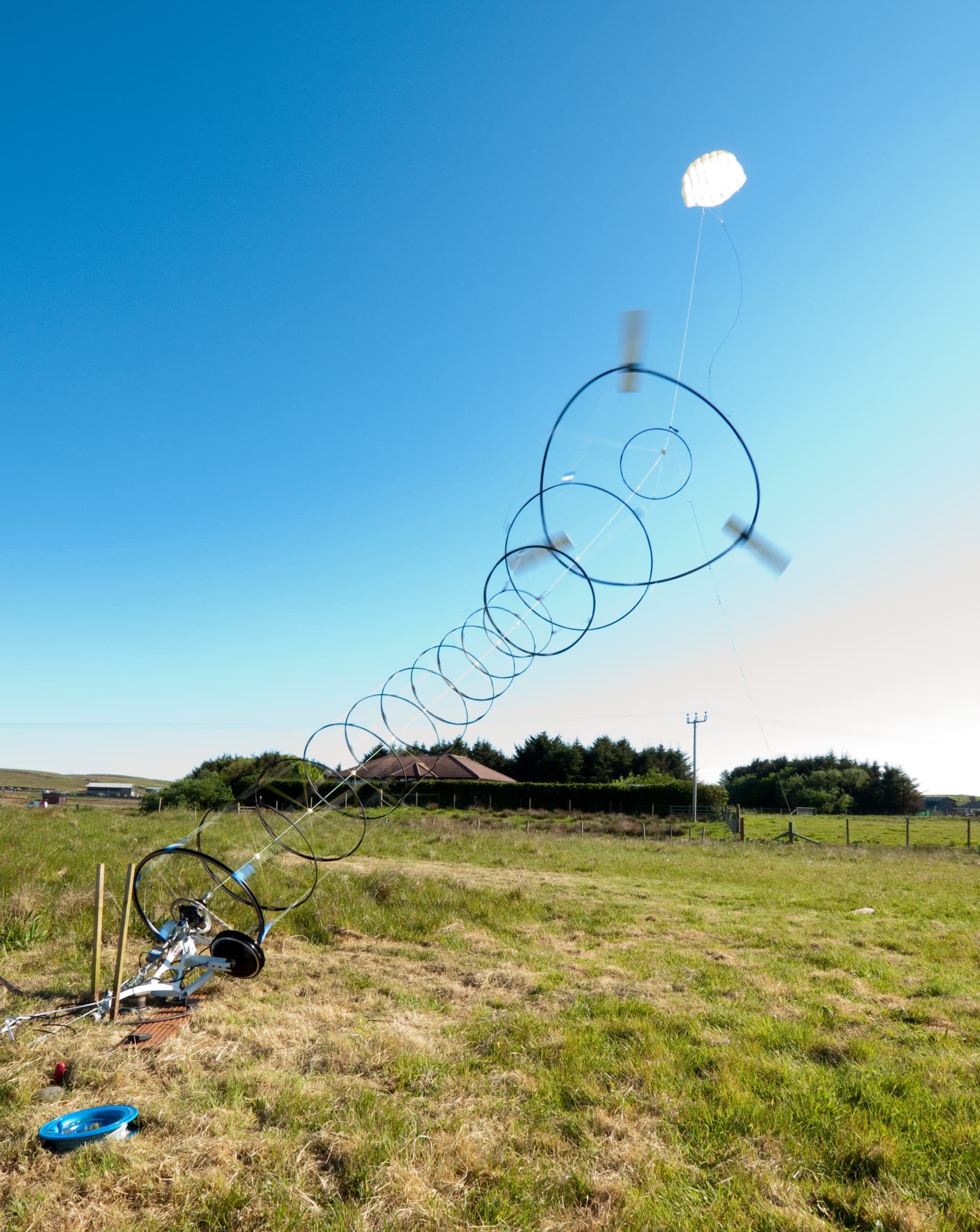
The tilted ring drawing is structurally somewhat like the device on my old FR2975445 patent that is represented in the video below, and called Wheelwind:
")
Wheelwind could be the tilted ground station for a giant Daisy with one rotor, offshore, and also onshore where the generator (in green on the video of offshore version) and the power take-off (PTO) tilted ring move on a horizontal circular rail to face any wind directions. In this way the blades of Wheelwind are replaced by spokes or/and diametrical ropes. The ring could also be built in Tensairity ™. Its weight is partially supported by the ground via the generator (as for the initial device).
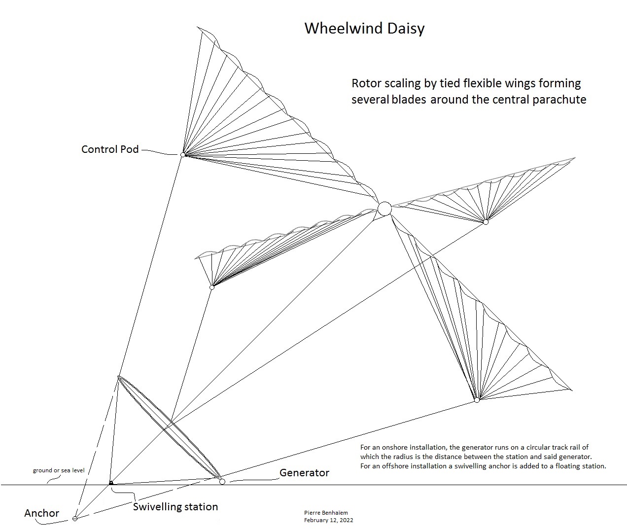
For Wheelwind Daisy, intermediate torque rings are not useful because the height becomes high when it scales up. Such torque rings would be too heavy, and would not be supported by the ground unlike the PTO ring which is supported by the ground generator.
Scaling of the rotor is achieved by implementing tied flexible wings.
A sketch of Wheelwind Daisy below:
There is therefore already a 1 kW Daisy range for electric cars; soon a 10 kW range for the home; and later for utility scale.
1 Like
A PTO wheel made with rope instead of steel spokes.

This is Adam from Tarty Bikes the genius tech who made the stub axles and thrust bearings setups I’ve been using.
2 Likes
Two or three days ago I noted this:
By a variant the ring is an annular rope assuring the transmission in Laddermill way. Said rope ring also includes diametrical ropes facilitating round shape cohesion. A parachute would fill said ring in order to add some lift and above all to assure a structural circular shape of said ring. The generator resistance facilitates lift production and stability as for a ballast in the bottom of a parachute kite.
Its interesting. Weight saving for bikes.
I woud opt for a sewn loop rather than knots, and mind the loop radius at either end… I guess one loop could account for two spokes.
1 Like
This vid got me re thinking…
Will auto-parametric resonance be a limiting factor in torque system scaling? Or will we be able to predict or sense and avoid with a line length or speed tweak?
Or in other words
Will kite turbine design be prone to wonky wobbles which result in boingy pulsing?

1 Like
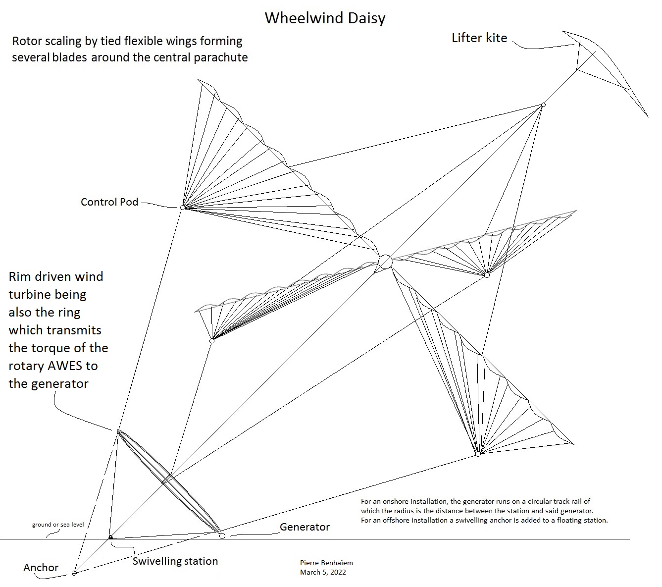
According to a variant, the ring which transmits torque from Daisy AWES is also a rim driven wind turbine, as for ASWES on the video.
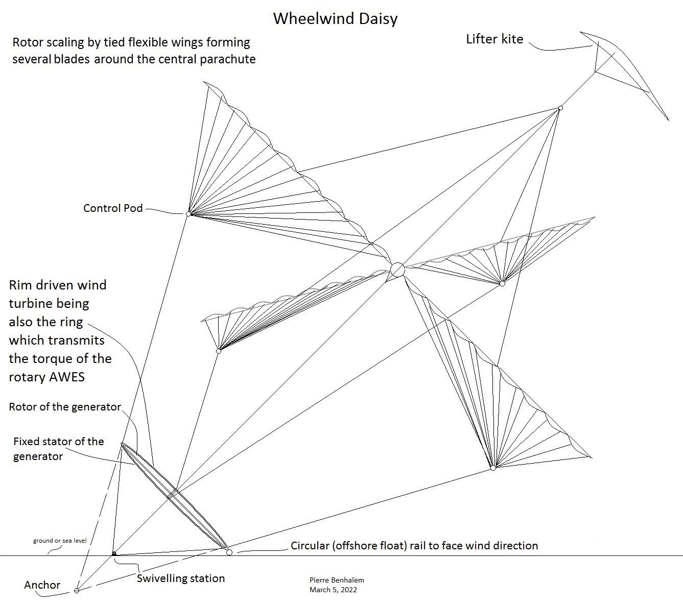
A variant with an annular generator (being also the ring for torque transfer transmission):
For a torque transmission system where, -
The kites can tension the rotor perimeter with their flight path
Is there any advantage of modulating flight dynamics to encourage a more wedge shaped flight path?
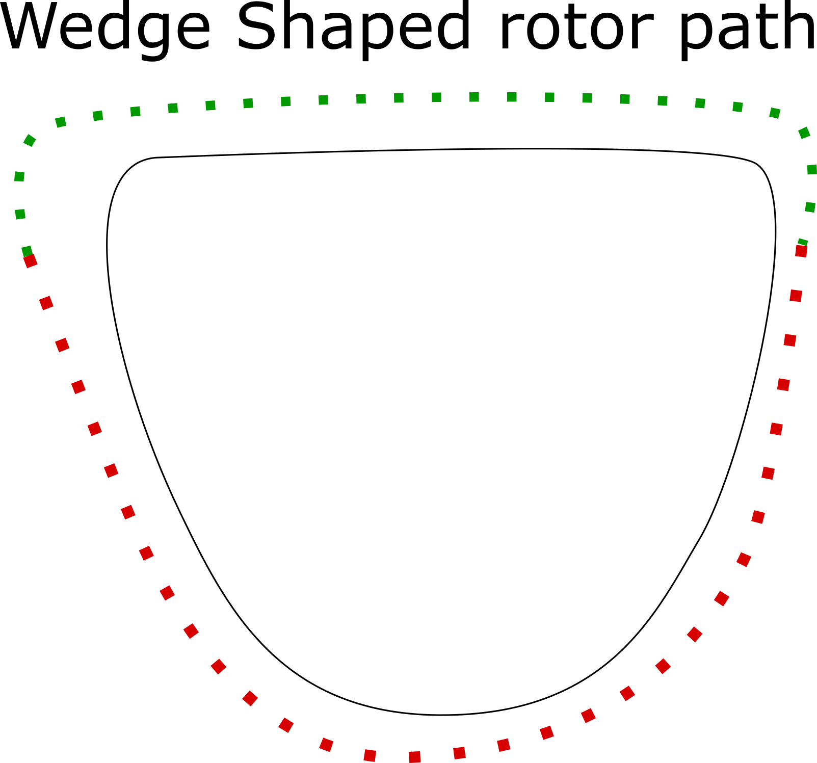
So , let’s say the kite bridling is fairly constant banked with the tips down…
With this path are more kites contributing to lift along the long top (Green) section
(you still have to fly the same overall loop width)
Is there maybe another potential advantage from this shape in terms of number of kites at altitude, line drag, land use?
Maybe controlling the elevation angle without airborne actuators…
1 Like