Why not concentrate forces in a single point for the gear… From what I understand a gearbox like this is commonly made as small as possible with the strongest materials (steel). I dont have a new design ready, but this is my initial thought
Hmmm… all designs lead to @dougselsam’s design (the superturbine)
Anyways, the design does not withstand torque at all…
Yes. And the inferior ring of the Rotating Reel transmission is usable if it is a ground rotor, the superior ring being the flying rotor. Both rings in flight are likely a wrong solution.
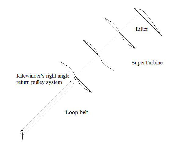
SuperTurbine ™ central shaft version (that @dougselsam built) seems to work better. It could have a rope-drive transmission a little like this to reach higher altitude, ceasing to be SuperTurbine ™ as such due to the additional transmission:
OMG disgusting.
That’s hard to look at just after lunch.
What a total abomination of a drawing.
Kill it. it is the kindest thing.
I’ll sketch something on my phone.
Ok
Hmmm maybe taking sketches as proof of performance isn’t our best route to progression.
I don’t think any reliable declaration of suitability can be based on those sketches.
One difference in our perception of utility is how I see 2 anchors as much preferable to 1
That does not work well, above all with a stacked network kite rotors of which the transferable torque depends on the axial force. So the rope drive should be as an extension of the axis of this tilted turbine in order to benefit from the axial force which allows its correct tension.
Yeah, I knew it was an old idea, and he has a good disclaimer of you could use any type of rope as the pulley rope.
And the priority dates were not long after I’d demonstrated and published video of a rudimentary rotary kite turbine and discussed just such a system possibility.
Leo has thorough patents.
I don’t know if you are able to know if patents are good or not. A clue to help you: in a search report, documents X are of particular relevance, taken alone; Y, the same but in combination with another document. X and Y destroy the patent if there are no observations or/and no new claims from the applicant. Documents A are not considered of particular relevance. As example in FR3034473 (Rotating Reel) there are only three A. https://worldwide.espacenet.com/publicationDetails/originalDocument?CC=FR&NR=3034473A1&KC=A1&FT=D&ND=3&date=20161007&DB=&locale=fr_EP.
Very interesting technical arguing. Are you talking about AWES, or are you saying there was too much mayonnaise in your lunch?
Why are we discussing terrible concepts? (referring to figure 1).
1 - using a rotating reel system and then having tether tension on a third tether is a recipe for high drag and low power capacity
2 - how on earth would you build that
3 - what if the wind direction changes
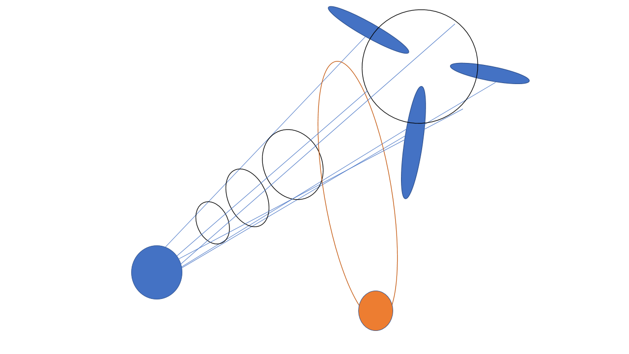
So the lack of belief in demonstrations or pure simulation of physical systems has annoyed me.
So I’ve revisited an old simulation system I built in 2016 and recorded it.
Nothing fancy, just soft architecture and force vectors
I’m working on a much updated version for AWEC2019
Who knows how much distraction I’ll have to endure in the effort.
The figure 1 is similar to the system sent by @Rodread’s phone. There is no rotating reel system in both. Both are unworkable as I already mentioned.
In the other hand discussing of these concepts allows to see that tensile rotors don’t work well with rope drive transmission in any way as I already mentioned, even by the concept (including flying rotating reel version) in the drawing I provided before.
The mentioned features in all the discussion would allow to know better the difficulty to scale as torque transfer system, due to deformations in sudden wind changes. And in yoyo mode (I suggested) the recovery phase would likely lead to collapse (as I suggested).
Rotating Reel is a transmission system using ropes, with a bevel, a ground horizontal rotor, a flying tilted rotor, with two simultaneous motions: the rotation of both rotors, and rolling and unrolling from reels while the flying rotor remains stationary.
No, @Rodread, it is not a story of single line or several lines. It is an affair of the transferable torque by a system comprising both tensile and rigid elements leading to possible deformations with higher loads.
Deformation of a soft system means nothing in terms of damage. As for control
A tensile inflated rotary system whose blades are moving much faster than the wind… well that’s going to cope well with variation in wind. A back-drive-able soft system fairs even better in coping with gusts. A system which can sense from the groundgen PTO what state it’s rotors are in, That’s going to do well. A system stabilised to a larger field of supporting lift architecture which is responding to the field average whist maintaining an ability at isotropic lifting behavior… That will really help. Most of that isn’t even smarts.
You have a real problem with this system and that’s fine by me.
Let’s agree to disagree. If you want to argue. Bring some meat.
The large lifter kite can have 2 tethers each connected to a Daisy train. If the kite is stable then the ‘thingey’ will be stable. The 'thingey can be a frame, strong enough to support bearings and pulleys.
Referring to the model posted in 73 Network Kites and Daisy network kite rotors
It sometimes collapses using different initial parameters.
The set of workable soft architectures wasn’t being recorded by that model, only single configurations were demonstrated at a time.