Or a limited torque, as for TRPT SuperTurbine ™ using also rings as torque transfer mean. It is the reason why for years this does not exceed a few meters of altitude.
Lets have a look at another example, of the same simple kite network idea reconfigured, scaled with more kites, but this time using a slightly different initial kite force alignment to the net,… Remember this is a simulation of pure soft line and realistic kite forces which comes to a static balance after simulation
Pierre: Nice Patent. It illustrates why I say " All Roads Lead To SuperTurbine™".
Whatever anyone comes up with, whether they want to call it a carousel, a kite, a tethered airplane, anything, may start with any movement but will end up going in circles, crosswind, and if it works well it will make sense to stack them, and voila! SuperTurbine™ in some form. Not that complicated.
Yep all sewers lead to Rome …
So the rat said in the Horrible Histories - Rotten Romans film we saw today. 
Yes all good rotary AWES owe a degree of gratitude to the superturbine. 

But it wasn’t the definitive description, the be-all and end-all of scalable rotary AWES.
There are several important factors missing in superturbine descriptions.
Crucial for all of these designs is torque & how to avoid letting it kill the shaft.
1 Like
Yes and no. The stacked rotor turbine discussed here is already a SuperTurbine ™. The only innovation is using rings for torque transfer, and seems to show severe limits.
Thank you for the compliment, coming from a true expert in patents.
You might be right @PierreB …
There were certainly flaws in the old version simulations.
It was close but Not a properly soft line sim post 82.
Would you like to check through the newer versions of the simulation software?
It may help you balance the severity of your judgements
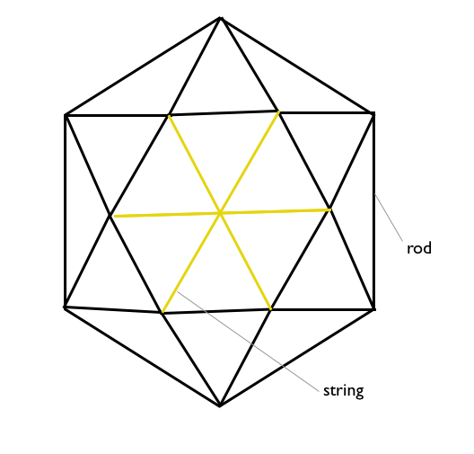
I might be repeating myself here, but: Why do you use rings for Daisy rather than n-sided “polygons” with straight edges. Ie straight rods connected by ferrules? One would think that should keep the shape better, as a ring is already bent and thus will be prone to further bending with force, while a straight rod will not bend as easily when subjected to force (until it buckles). The aim seems to be to keep the tethers from compressing radially, thus my question about star vs ring structure of the spacers (is there a better name for these parts? I am using “spacer” as they ensure space between tethers). So we actually have at least three spacer options:
- ring
- polygon
- star
And then I might suggest a “lattice” arrangement (just the idea, the shape itself is just improvised and unoptimized)
My point being with all this, that the weight of each spacer limits the maximum altitude of the rig and should be optimized quite a lot imho.
1 Like
Making latticework-like structures instead of rings has already been discussed. That could improve the rigidity compared to the ring but by increasing the weight in flight, aggravating the weight penalty by square-cube law. Each platform will weigh tons in multi kW range, making the set heavier than Makani M600 for a same given power.
Another solution is no ring or similar for torque transfer in flight, the only (wider to reach higher altitude) rings being the ground rotor and the flying rotor(s).
Hi @tallakt, nice clear diagram and description of what you are asking, thanks.
I like the term spacer.
In practice, it was really easy to build a spacer ring in a compressed cuff. So I did that.
In the simulations, I use polygon spacers. I’ve been testing prints for node cap elements for a new TRPT spacers. (TRPT only e.g. the lower part of a Daisy where the spacers are - not a kite ring part)
Because of the pre-bending in the spacer rings (as tested), they’re not as efficient (strength to weight at resisting compression) as a polygon spacer, fixed into node endcap’s - ferrules. Also at the small diameter I used (TRPT spacer only) 5mm carbon vinylester is really stressed and close to it’s minimum bend.
In your diagram of the lattice arrangement. I’d suggest getting rid of the innermost yellow strings and replacing the inside darker rods with strings also upping the node count. Tie it carefully from the inner ring so as to avoid rubbing. This reconfiguration would remove drag (polygon is more draggy than ring …until rings start deforming.) and allow better mass scaling.
Rods the full circumference are only preferential where you don’t have a means to expand the tethers.
A stack of M600’s inside a tensile rotary net set would be sweet to play with.
1 Like
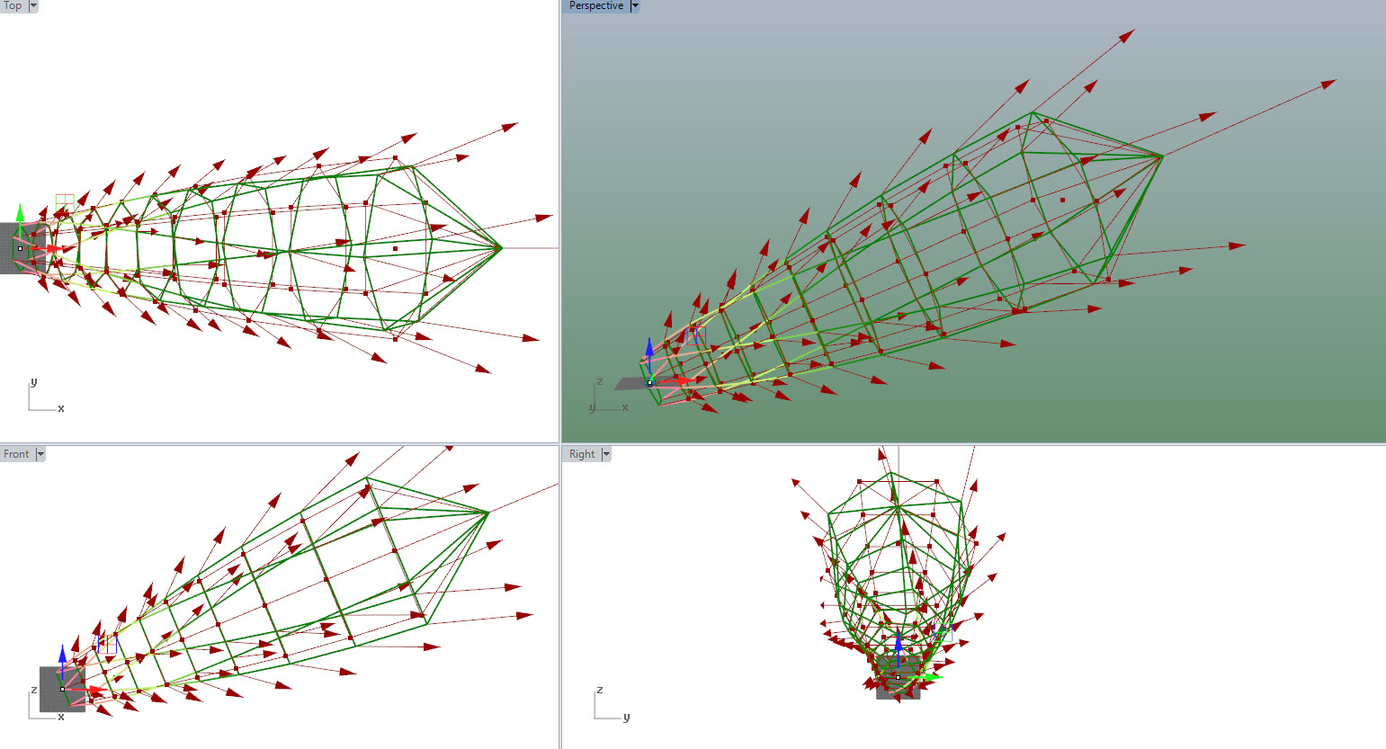
The analysis I’m doing at the moment uses purely line (string if you prefer) for the whole net.
Depending on how a kite loads each node, you will crush or maintain form to different extents.

sometimes they crush

sometimes they grow
The model of soft net torsion simulation I was working on seems very adaptable.
Here, It’s reconfigured to simulate a situation much more like the single rigid wing tests.
All of the net lines are still soft. The top ring compresses noticeably (~12%) the third ring also compressed ~3%
1 Like
So, as per the sim model… I’m now going to attempt a turbine & TRPT without using a central lift line.
So it’s an evening in the loft, stitching these lines onto these frames.

4 Likes
A lot more than 1 evening later
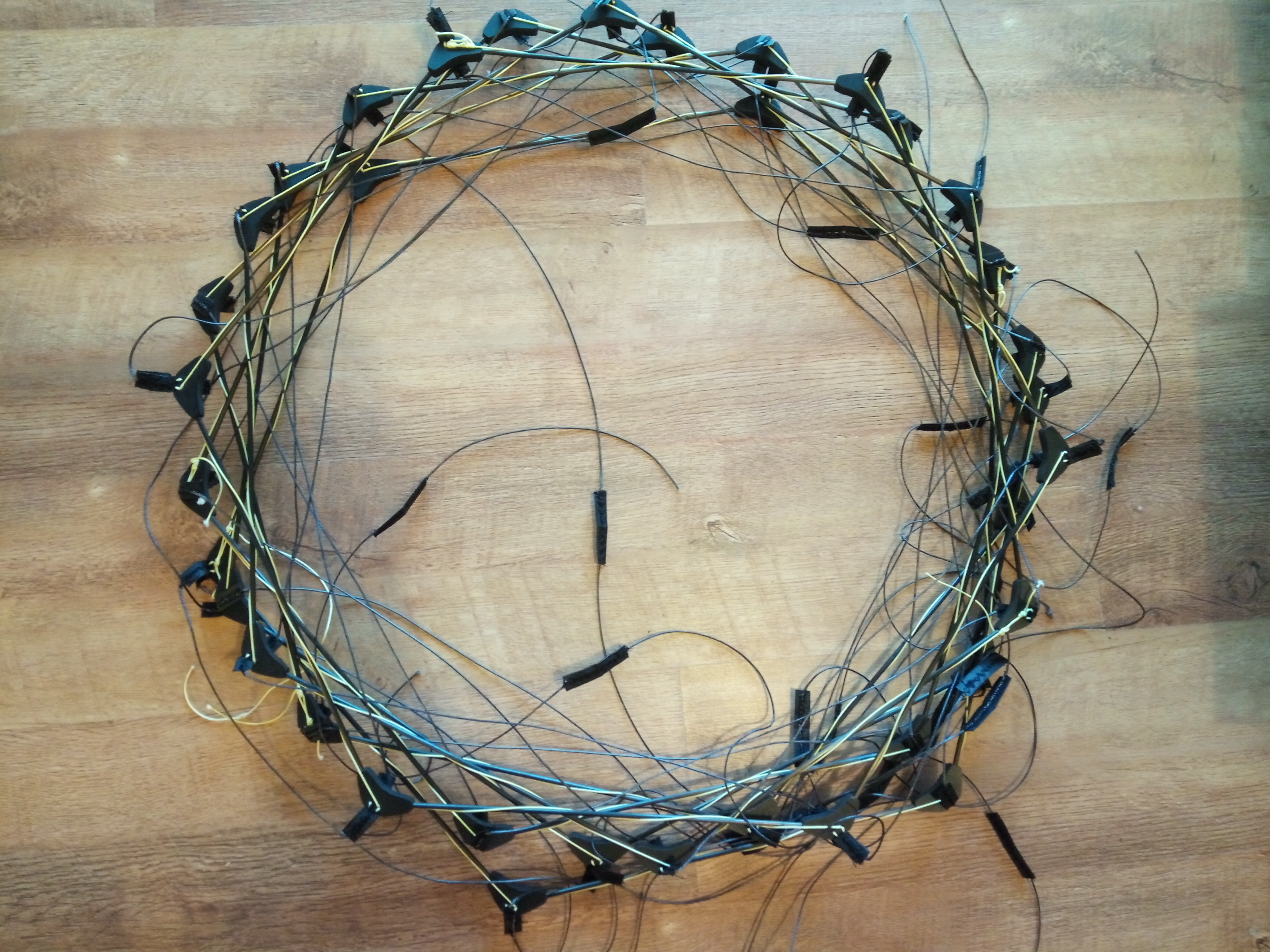
Still got to get end attachments.
I think it could do with bar section rods and better web transitions.
2 Likes
Looks great. I seems to be that it is the weak point of your tech. I mean this looks uneasy to set up, build operate, store. Anyway it looks better with time. At some points you realise that great things happen by small incremental steps. Small improve a 100 time and there it is :something great. Keep pushing rod
3 Likes
Yeah, given the right circumstances, there’s a lot of planned changes coming for the transmission form. For now it works fine for the purpose.
Now that this is a hexagonal form without spoke lines, there is a snag possible, but it comes out easily in tension.
Making the thing is easy… just sewing, a plastic cut, a drill and carbon rods.
The rods could be better as bar section as they wouldn’t allow the hex rings to twist out of plane… however… tension should alleviate this a bit…
There’s a lot can be improved on this one
1 Like
I’m working on ideas for a new introduction video
This is a slide set I’d be talking around…
Although this is a bit more stand alone than a video would require.
What do you think?
Video SLides.pdf (5.3 MB)
I like the backline. Consider a “teabag” anchor consisting of a drogue or streamer with enough mass to mostly stay down, so the whole rig can rotate passively.
TUDelft’s AWE classification schemes are very incomplete, no place for Kiwee, crosswind cableways, and many other AWES teams and architectures. SomeAWE and EnergyKiteSystems do far better at classification.
The back line is perhaps used to stall the turbine and lower it at an edge of the wind window.
Yes, of course, side-pull is the dousing method. A teabag-drogue allows side-pull without disengaging an anchor-point.