To be more precise the aerodynamic moment can be solved by the axial aerodynamic force which comprises both lift and drag.
The Required Line Tension of 1391723 N can be the required axial aerodynamic force (lift and drag) to solve the 231953.8 Nm Rated Torque, possibly comprising the kite lifter as I mentioned.
However the required axial force 1291723 N (about 130 tons) is a huge value in regard to the 231953.8 Nm Rated Torque. By comparison for some Parotor configuration (chapter 22, pages 569-570: Ground rotor diameter dg 50 m, Flying rotor inner diameter dk 40 m, Flying rotor outer diameter dk,o = 70m, Distance between rotors lK 100 m) the aerodynamic moment (torque?) of 683 kNm can be solved by the axial aerodynamic force of (“ONLY”) 250 kN (of which lift = 125 kN, and drag = 217 kN), but with only a single layer.
Perhaps for Daisy it is the result of the part of transferable torque layer after layer on 12 layers of kite rings, leading to an increasing part of the Required Line Tension (axial aerodynamic force (lift and drag)) proportionally to the Rated Torque as the number of layers or the total height increase.
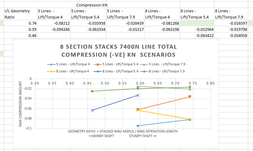
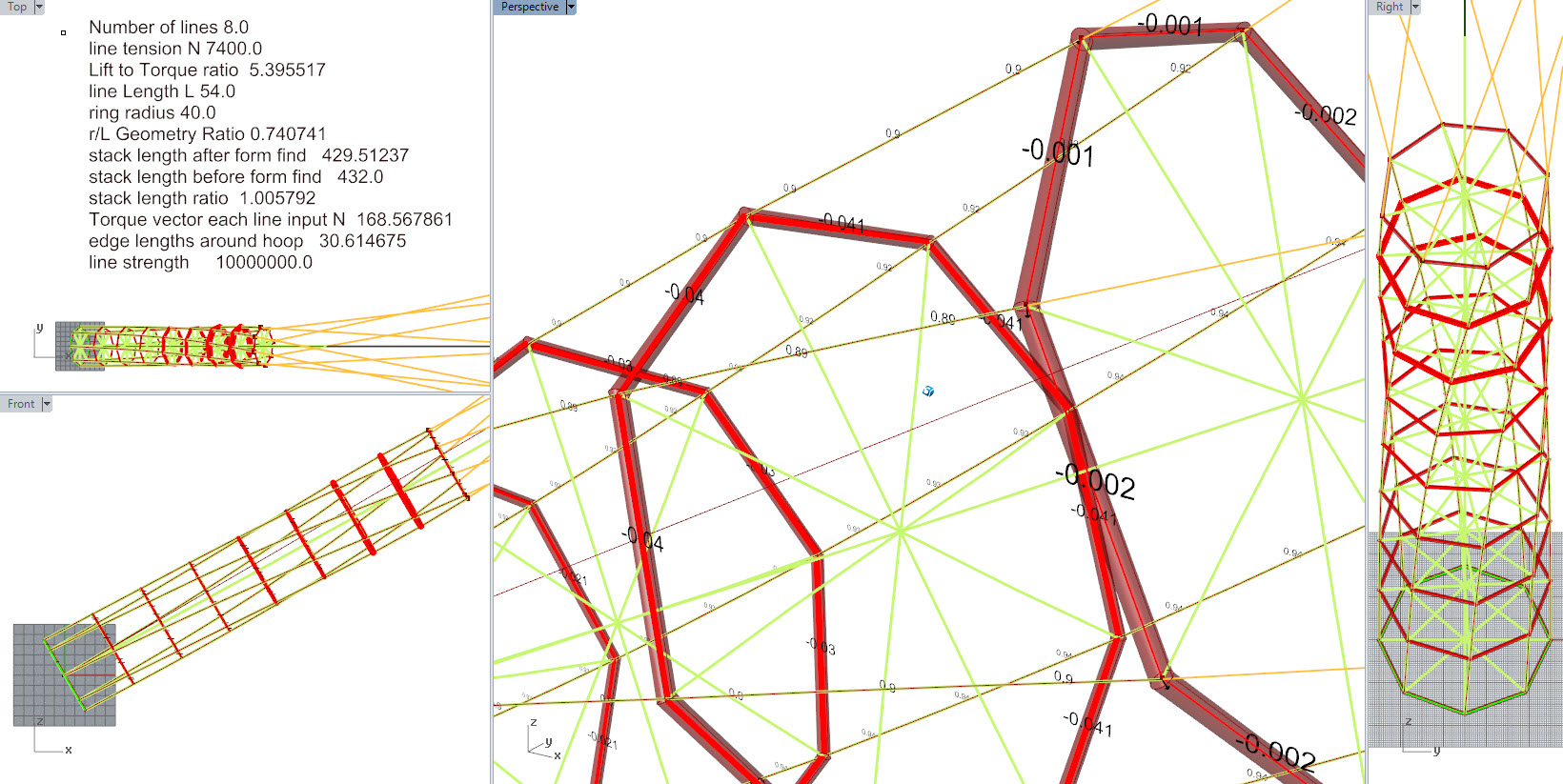
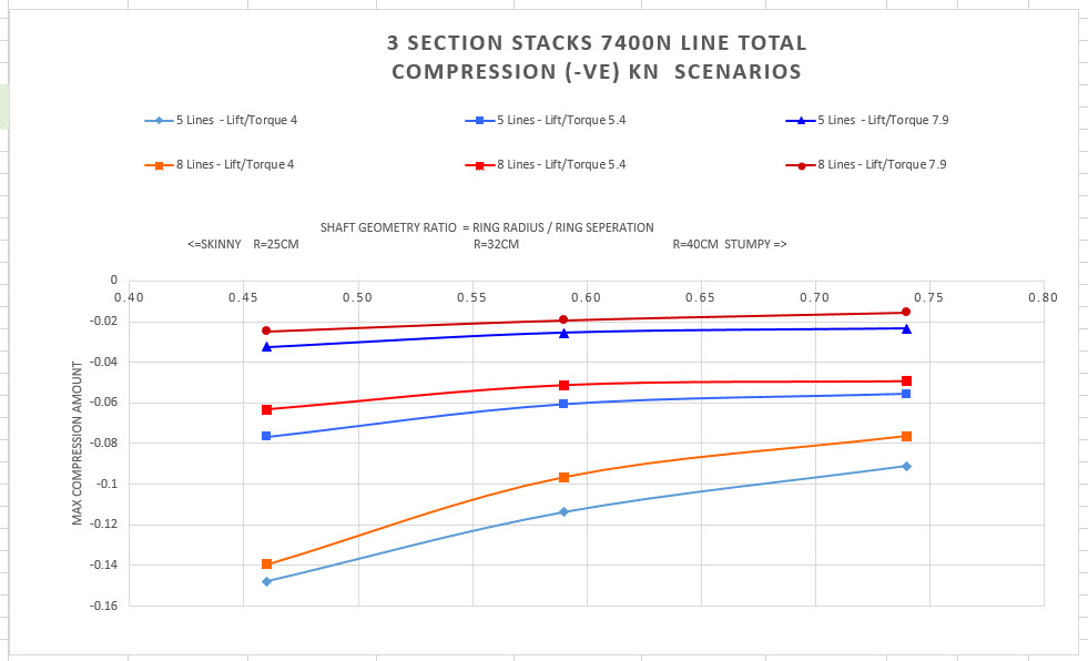
@Rodread provided some calculations of the transferable torque between 2 layers :
Yeah
And check out how small the shaft diameter is
Tiny
It’s based on the existing shaft.
Also the lift to torque ratio was specified at the start.
Ia there any account here for rigidity of TRPT? No.
Hence tonnes of lift needed
Did I mention not to rely on that calculation.?
Try link to the nicer graph too.
Remember previously I explained my open source system plans and then you adjusted them to take out a para rotor patent…?
No this time cove.
Details details
This remark is misplaced. I have already a patent about rotating reel as you know, and with a good search report (only A):
https://worldwide.espacenet.com/publicationDetails/originalDocument?CC=FR&NR=3034473A1&KC=A1&FT=D&ND=3&date=20161007&DB=&locale=fr_EP
The figure 1 is reproduced in First Year Review in page 69.
Moreover Daisy could be seen by @dougselsam as a SuperTurbine ™ variant. Rudy Harburg’s patent can also be seen as a relevant prior art.
I’m just trying to analyze which AWES can scale. It looks like the higher Daisy is (for the same diameter), the higher the axial force / torque ratio. It is a question of proportions between the diameter and the height, but also of the number of stacked kite rings allowing Daisy to reach a high height/diameter ratio, the price to pay being the high axial force / transferable torque ratio.
For the rotating reel parotor (with only one rotating kite), it is hardly different as the diameter is roughly the same as the top height for an optimal transferable torque with the least axial force (lift and drag) possible. Stacked Daisy is thin while not stacked Parotor is fat, but the principle of transferable torque is similar: see the figure 22.18 (chapter 22, page 571) showing that higher is the distance between the flying and the ground rotors, higher is the axial force / transferable moment ratio.
Perhaps I could correct it a bit, as the axial force / torque ratio looks to be the same (about 6) for the 1000 kW sample (on Network Kites and Daisy network kite rotors - #34 by Rodread) than for other smaller examples, likely due to similar proportions.
However said axial force / torque ratio looks to be very high. Using the 1000 kW Daisy stacked kite ring unity as a reeling yoyo system, that becomes:
Required Line Tension = force = 1391723 N. This force is multiplied by reel-out speed = 11/3. Then the result is multiplied by 4/9 due to the squared apparent wind speed less reel-out speed.
Result: 2.267993 MW.
Daisy designs (which were mentioned but described poorly in your patent @PierreB ) were the first hollow axis autogyro kite turbine … There was quite a lot of potential configuration presented openly on the old forum as soon as I devised it. As for priority dates yes - Rudy Harburg #1 Doug S#2 My yahoo open work#3. Para-rotor came later. Daisy was the first hollow axis autogyro kite turbine. And quite a lot more besides. Moving on.
Maybe @PierreB you should upgrade to ollies 2nd year review for a discussion on the differences in torque transmission
The analysis you did with Roland figure 22.18 (chapter 22, page 571)
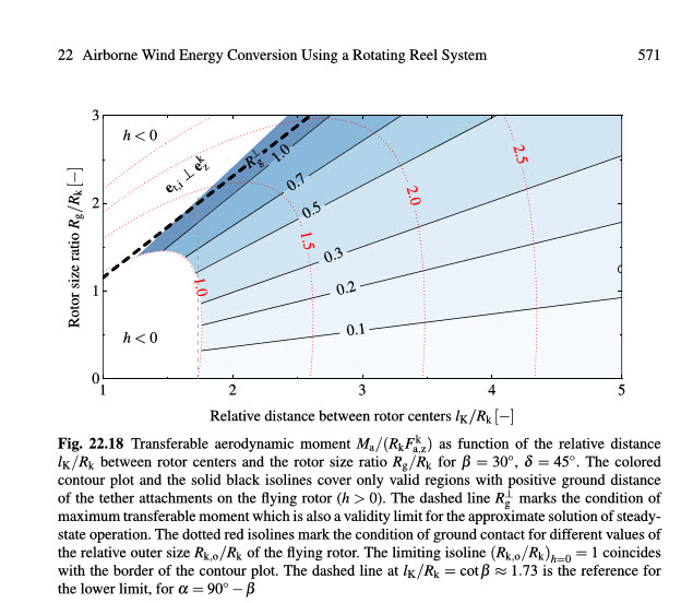
Describes how a single ground plane PTO rotor interacts with a single flying rotor kite autogyro in a single configuration
That’s quite different to a stacked and aligned system analysis
Or soft rotary kite system scaling using >100 kites transmitting torque over a soft line network
Like

Yes it has limits as partially shown in

but the benefits are huge.
Ask Rachel…
She’s waaay more clevererer than me
@PierreB
You’re suggesting a method of
holding the torque at the same time as generating from Yo-Yo.
Sounds like the 2nd generation mode of a para rotor…
I can’t wait to see it work.
Make sure to keep us up to date on progress.
No, it is only a yoyo version. It is easy to know it by the numbers I provided.
[/quote]
No, it is not like the 2nd mode generation of Rotating Reel Parotor of which the flying rotor remains stationary.
It is only a suggestion for a yoyo version as the axial force is greater as the moment. But it is for later.
Indeed 2.3.3 page 25 Parotor: “the Parotor uses eight soft kites on a single rotor with a TRPT. In this case the TRPT consists of four tethers equally spaced around the rotors. There are no rigid compo-
nents other than a rotor at each end of the transmission.”
I agree this description. And you? Do you agree the Parotor is a TRPT?
I said:
Similar does not mean exactly the same.
The main challenge of all torque transfer devices is the distance of the transmission, so the top height. Rotating Reel Parotor intends to resolve it by implementing a large rotor enough to reach high altitude, the price to pay being the difficulty to build a huge rotor without rethinking it. Stacked Daisy intends to resolve it by superimposed stack ring kites allowing to reach high altitude, the low torque in regard to the high axial force being the price to pay as I mentioned.
One mentions the prior art in a patent. By this one mentions the problems from the prior art. In the case of Daisy I mentioned possible deformations. I believe you confirmed it in some tests you related in videos.
You state it is the first hollow axis autogyro kite turbine. Can you justify it with a search report? File a patent and one will see.
I don’t claim Rotating Reel Parotor is the first hollow axis autogyro kite turbine. Even the first drawing shows a parachute between the wings-blades. The claim 7 indicates a hollow mast for another function, and this claim is connected to the first as it is a dependent claim. Fortunately there are experienced patent examiners who know the nuances and how patents work.
Your remarks suggest you don’t understand the principle of the Rotating Reel Parotor system as it is
as close to the NTS and KiteGen carousels as to Daisy or SuperTurbine ™ I quoted. So your timelines is nonsense. Moreover generally patents quote other patents as prior art. In a similar way scientific publications quote scientific publications as references.
Note I quote both Daisy and SuperTurbine ™ although @dougselsam considers Daisy as a SuperTurbine ™ The most crosswind kite power system? - #10 by dougselsam.
Patents exist also to avoid arbitrary remarks like yours, unless it is your concept of “open sharing” I don’t yet understand. In the search report there is no relevant prior art for what I claim.
Rachel’s multi-kite airborne wind energy systems (MAWES) are not torque transfer devices. I quote from the Introduction:
" The system class under consideration is that of rigid-wing pumping type systems."
In page 7: “The second observation is that in order to maximize efficiency, a fixed number of aircraft should always be distributed over as many layers as possible. This strategy maximizes the amount of available harvesting area.”
I think the invoked benefits are not quite the same as for Daisy, but it is a subject for discussion.
This yo-yoing Daisy calculation is based on a hugely suspect interpretation of a potential capability of a Daisy system. Who knows.? Change it to yo-yo, was Moritz’s initial impression too when I showed him a working kite turbine stack video. Yo-yo removes line redundancy advantages brought by network turbines. These calculations could be >100x out.
Yep, Parotor has a TRPT
so to highlight more similarity any TRPT works best (lightest) with wide diameters, short spacing between rotary rings and high line tension. Cool, Daisy has that covered. Only a short ring to ring section at the bottom, then expanding from there upwards. (Not a skinny main generating turbine shaft)
good.
Anyone can demonstrate the potential of how torsion can crush a tensile tube shaft by twisting their trouser leg. How to avoid the torsional compression of torque transfer over a tensile shaft is the real skill.
Ah, cool, I probably don’t understand. and yes it’s great to see KiteGen carousel mentioned here too (Massimo has loads of priority over me) A forum section “Parotor AWES” with descriptions we could link to in this thread if necessary would be good.
Yeah, I have trouble understanding the benefits of patents in many circumstances, especially this one.
That’s why I blurted out a whole load of initial ideas https://www.youtube.com/user/roddyread/videos?view_as=subscriber You’ll see a whole lot of ground plane rotary power take off design in that body of work.
Yes, you are right, Daisy is different to the pumping yoyo MAWES and maximum number of layers is not most beneficial for Daisy. Much Rachels analysis however implies genaral benefit to AWES from multi-kite designs.
You answer too fast. Please read carefully my patent and the chapter 22 about Rotating Reel system then come back in a month for this subject. Thanks.
Me, and apparently Moritz. The calculation you provide shows a huge axial force compared to the moment. And it will not be better as the height and the load increase. So instead of using the moment, you could use the axial force. But you can doing it later as you can try to go higher with what you call Daisy but is SuperTurbine ™. And I don’t promise in yoyo mode that will work well enough.
You just change your opinion.
Both use TRPT. And also SuperTurbine™ US6616402 fig. 88 uses TRPT.
I agree
I agree you don’t understand both patents and Rotating Reel.
A patent is neither a history book nor an image book, but a technico-legal document.
I will explain you quickly: the prior art is mentioned, and the given solution can be considered as new if the combination (even comprising known elements) gives a new concept for a product by trying to solve problems related to the state of the art.
@Pierre You have been wrong and off-topic in this thread.
I’m replying to the 6th edit of your post already.
I’ve read and reread your patents and chapter. Do you provide links to all of your patents on this forum? They are surely a means by which we can all learn. There, for the good of engineering development right? A tool for work to be recognised.
We must be wary though, Patents have historically been used for sinister purposes.
1 You’re argument is based on a baseless calculation.
2 Parotor uses a TRPT - I haven’t changed my mind on that.
3 Understanding the BENEFITS of Some Patents VS Understanding Patents - - That’s very different
4 Daisy Network rotors and their integrated TRPT have a maximal operating torque for a given geometric and mechanical set dynamic. Maximum wing efficiency can be achieved without torque destroying a stack.
There are two aspects of network kites I mentioned from Network Kites and Daisy network kite rotors - #32 by PierreB (post 32). I summarize.
- TRPT SuperTurbine ™ can be seen as a network of kites forming rotors then a stack of rotors, then an unity.
- On Network Kites and Daisy network kite rotors - #37 by PierreB (post 37) I asked a question about the network of the whole, thinking it is not a realistic solution due to possible various winds within the operation zone.
A calculation about an unity was provided on Network Kites and Daisy network kite rotors - #34 by Rodread (post 34), then the following off-topic remark I quote again from the post 44:
The translation of “open source system plans” is plans on the base of @dougselsam’s US6616402, of which his TRPT SuperTurbine ™ on fig. 84 and some other figures, + the network of the whole which is not in my FR3034473 patent https://worldwide.espacenet.com/publicationDetails/originalDocument?CC=FR&NR=3034473A1&KC=A1&FT=D&ND=3&date=20161007&DB=&locale=fr_EP.
I see in this remark a not appropriate answer concerning the likely unrealistic whole network due to wind changes, rather than a concern about the integrity of what is pompously called as “open source system plans”.
And just after:
It is surely on-topic ![]()
Please read the quick calculation of yoyo version:
Of course one should take into account of the reel-in phase. If you have a doubt Moritz or @rschmehl can confirm the pulling transmission can be longer as the torque transfer. But that doesn’t mean TRPT SuperTurbine ™ doesn’t work as there are other factors like a steady-state transmission.
You said something inducing the reverse in a “personal” message of which you have already published a large part on the forum.
You change your opinion a time again. Sometimes generally patents as bad, sometimes only Some Patents are bad.
Dou you mean TRPT SuperTurbine ™?
@PierreB
The 2 aspects you summarise
1 Yep, Superturine depictions can be seen as a rudimentary network of kites. No problems with that. Some depictions of superturbine show very complex outer network lattice. And some depict superturbine using a TRPT
TRPT — not my term — yes any Tensile Rotary Power Transmission is a TRPT
2 You did ask a question on post 37.
So far it works without in tests of stacks and in simulations of multiple stacks held together under lifting networks. The kind of lifting network shown simulated in very turbulent wind in the 3rd video on the first post in this topic.
You also mention a calculation about a unity post 34 (By unity can we be clear here please, Do you mean a collection of kites networked together in what I call a networked kite turbine?)
The numbers (not even calculation) presented in post 34 are massively unreliable as I’ve stipulated several times.
The chat in the last post was far from progressive after that. The quote was from post 43 actually. It still stands. My plans have been based on the discussions we were all having on the old yahoo forum. I had a bunch of original ideas … But Of prominence to me was how @dougselsam Doug highlighted the need to continuously sweep more area with less material at higher speeds, which was when I conceived and drew
Funny how it still looks kinda like what I do …
But the implementation has changed hugely since 2011
Anyway, the rest of the last post was either incomprehensible or shite.
Let me know if you clarify some sort of sensible statement or question.
Animations are not simulations.
These numbers were only a basis for some calculation. Pulling transmission goes higher than torque transfer, but produces a discontinuous power.
Indeed the passage related to your opinion change about Parotor using a TRPT would be clearer if I completed the nonsense you publish with the nonsense you send me as “personal” message.
Send your last “personal” message here and I will tell you.
My simulations were simulations thanks Pierre.
I appreciate you are trying to improve AWES by considering implementing a tensile rotor for yo-yo.
We have a more to do before a reasonably believable prediction can be produced for that concept.
And especially at that scale.
I’ll spare reposting again what I posted to you as a message and again as a posting if that’s ok.
Now let me get back to criticising my own work. The problem with that drawing in post 53 was the lack of networking on the driving kites would cause all sorts of unnecessary grief in a rough wind. I can say that after having tested flying over a really roughly turbulent field. The effect of turbulence on a spinning blade is lessened by its apparent wind.
1 Like
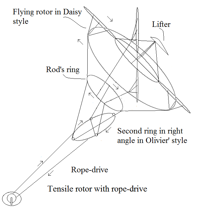
Why not connect the base of a Daisy system to a cable drive to take advantage of high altitude. I recommend 2 counter rotating systems to balance torque and provide more Daisy wheels. The large pulley will aid in providing high rope velocity which will improve the transmission performance.
DAISY TO CABLE.pdf (62.4 KB)
Ohhh looks a bit wobbly that flying table thingey.
might need a few more tethers, wheels and bits.
Another suggestion … Think it was Dave S … May have been me or AN other… Sling a hoop of knobbly curtain pulley line over the rotating lines, to take the torque off, to a ground pulley gen set orthogonal to the axis and downwind of the rotary anchor. Which removes the need to transmit torque down the rotary line set… yucky
I would love to have the chance to work on cable drive on another architecture. Which one could be the most appropriate for that, this I don’t know.
1 Like
The two rings undergo the load, preventing high scaling, unless they become rigid and heavy.
They are connected by ropes of which the length varies during the rotation, in Rotating Reel transmission style.