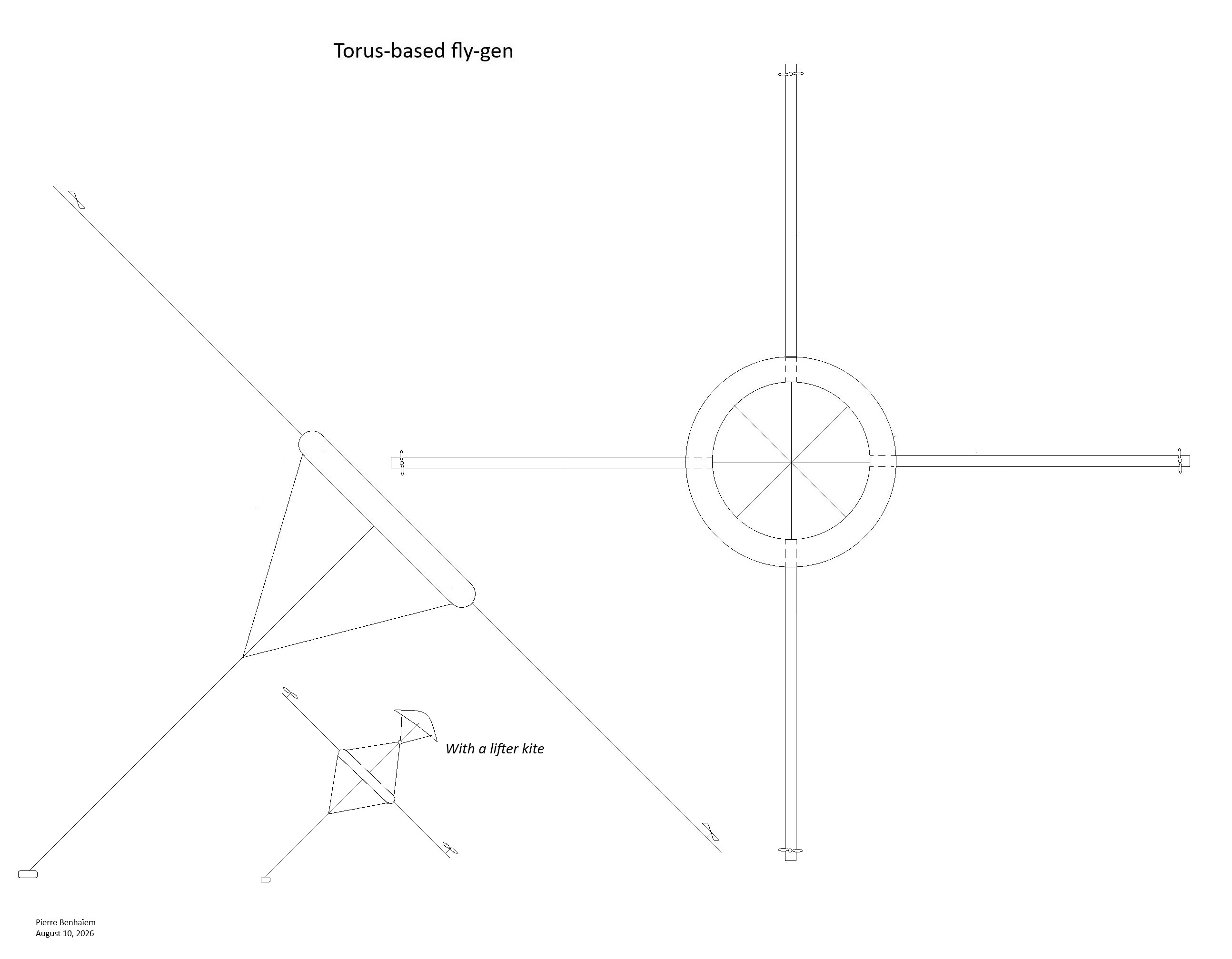
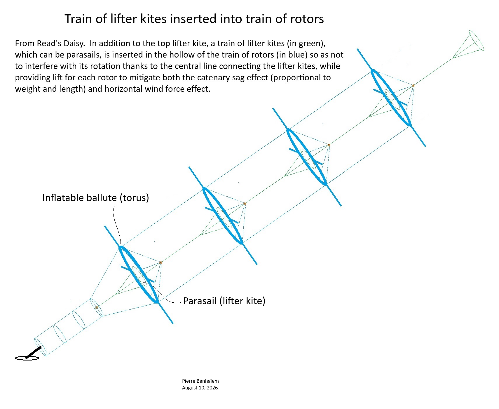
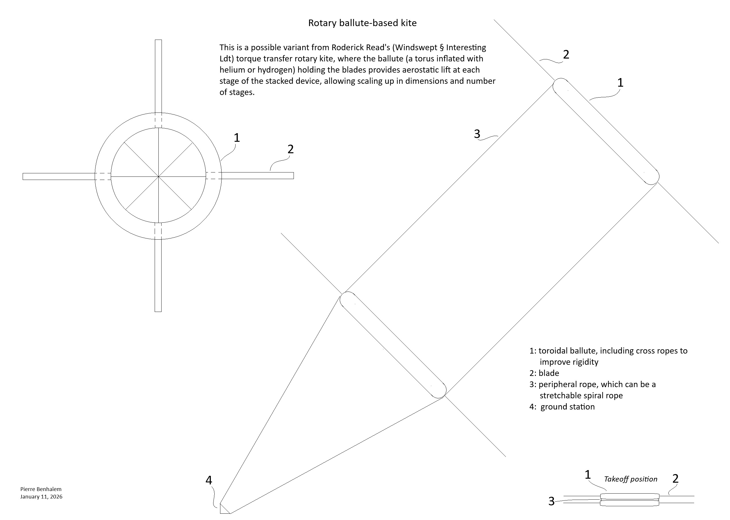
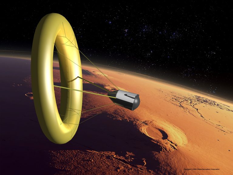
This airborne wind energy system (AWES) is a possible variant of the torque-transfer rotating kite turbine of Roderick Read (Winswept & Interesting Ltd) or Douglas Spriggs Selsam. Here the toroidal ballute is a torus inflated with helium (initially) or hydrogen (subsequently) that provides aerostatic lift which supports each of the stacked rotor units (and not just the last one with a lifter kite), thus increasing the number of units and therefore the total range. In addition, the torus can be of large dimensions, which allows for increased scalability and a larger swept area.
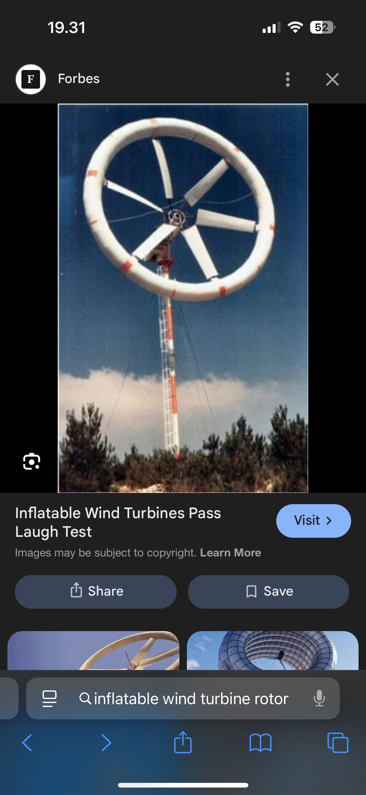
Indeed Winflex uses an inflatable torus, but the blades are inside while they are outside for the rotary ballute kite which is a TRPT like Daisy. That said the attachment of the blade around the torus in the Winflex manner can be applied.
I use a torus for several designs. This torus design could be more appliable than some others.
Nevertheless, for a large number of stacked units, the angular rotation speed of each of the rotors should be identical. One risky solution: placing increasingly larger rotors for increasingly stronger winds. Another solution: arranging to capture the angular speed of each rotor to equalize it for all rotors, preferably using methods less complex than variable pitch, possibly by means of telescopic blades or aerodynamic brakes.
A tilted ballute could become a tilted rotary ballute-based kite, by adding blades and TRPT, as it was achieved in a certain way by the initial Daisy design.
In previous posts, I had mentioned the catenary sag effect as a factor that could limit scalability by the number of stacked rotors and their mass, due to the mass causing the middle of the stacked rotors to bend toward the ground, with the lifter kite at the top alone not being enough to counter this effect when the set is very long.
Moreover, the lifter kite should also allow the whole assembly to lift, but, for long sets, this seems difficult due to the tilting effect of the horizontal wind force, even though lift aggregated with that of the lifter kite is observed.
It seems that ballutes (torus) inflated with helium or hydrogen could help overcome these difficulties and lead to larger dimensions, both in the diameter of the rotors whose blades could be twisted, and in length by the number of rotors.
But then I see another problem that might not be one. How will the whole system behave, knowing that the rotors will be subjected to winds of different directions and intensities? Will the rotations self-regulate, at least up to a certain threshold of irreversible torsion?
This problem can also be posed (and maybe it has been) for long stacked Daisy.
I’m going to go out on a limb here and say
Old @Rodread was likely wrong on the rant I held on catenary sag effect
and @PierreB was likely correct
There’s going to be a droop in the middle of the length of a chain of common axis rotor kites even though they supply more vertical lift than their mass and associated transmission parts need
I am hoping I’m wrong but it does seem intuitively correct
I have not simulated this yet
Can’t say I remember having witnesed it (Genuinely been that long since I flew one )
A brief history to lead towards an inflatable version with helium or hydrogen (which may be possible because everything spins at the same time, reducing the risk of static electricity by contact).
The catenary sag effect was very visible on Serpentine because of its weight, and not visible on three-rotor-based Daisy. But one can suppose that for very long lengths, it could occur.
An analogous solution could perhaps be possible with the currently discussed version with inflatable ballutes, which would generate aerostatic lift at each rotor, capable of mitigating or eliminating the catenary sag effect as well as (to a lesser extent, or else on a large scale with volumineous ballutes) the bending forces of the wind. Thus, the lifter kite located at the top would have less work.
It remains to be seen whether the whole system would self-regulate with different winds for each of the rotors. Perhaps this could help to start knowing it. And also the drag of the ballutes should be reasonable (although that remains to be seen), knowing that the maximum speed would be at the tip of the blades.
Some tests seem to show that the drag of a torus or ballute during rotation is prohibitive. Perhaps it would be better to replace it with a central inflatable disc to reduce drag, but it is not sure because even a thin throwing ring significantly slows down the rotation, all the more for a disk. Airborne solar wind energy systems (ASWES) - Lounge - AWESystems Forum
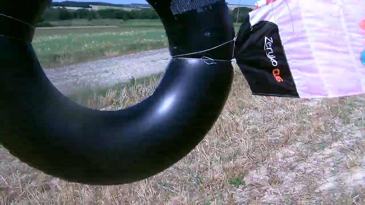
I just noticed that the rotary ballute-based kite has already been made, with flexible kite blades (video below).
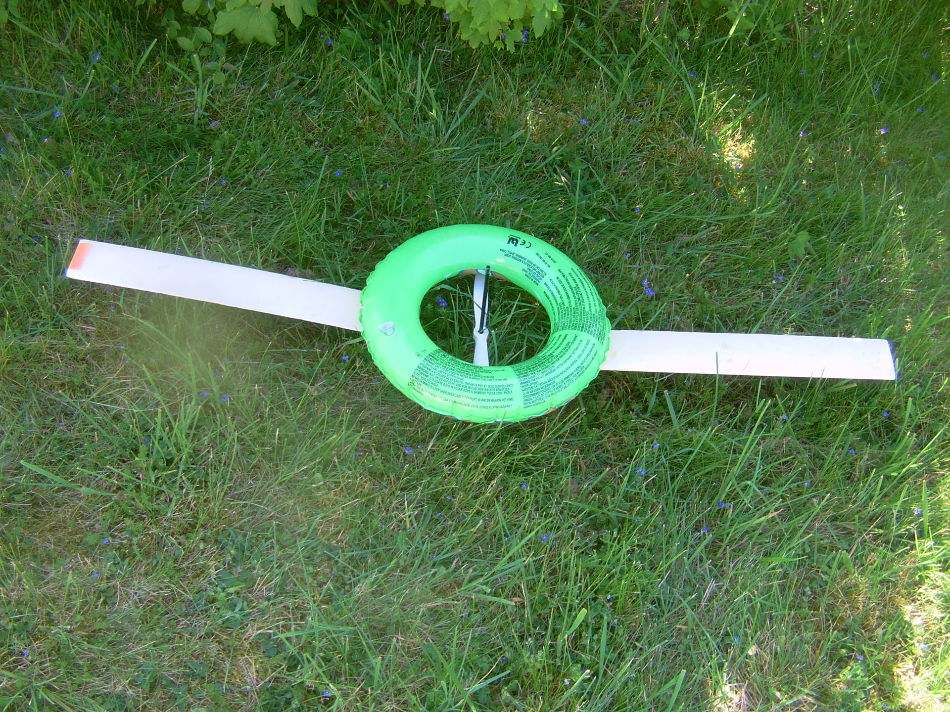
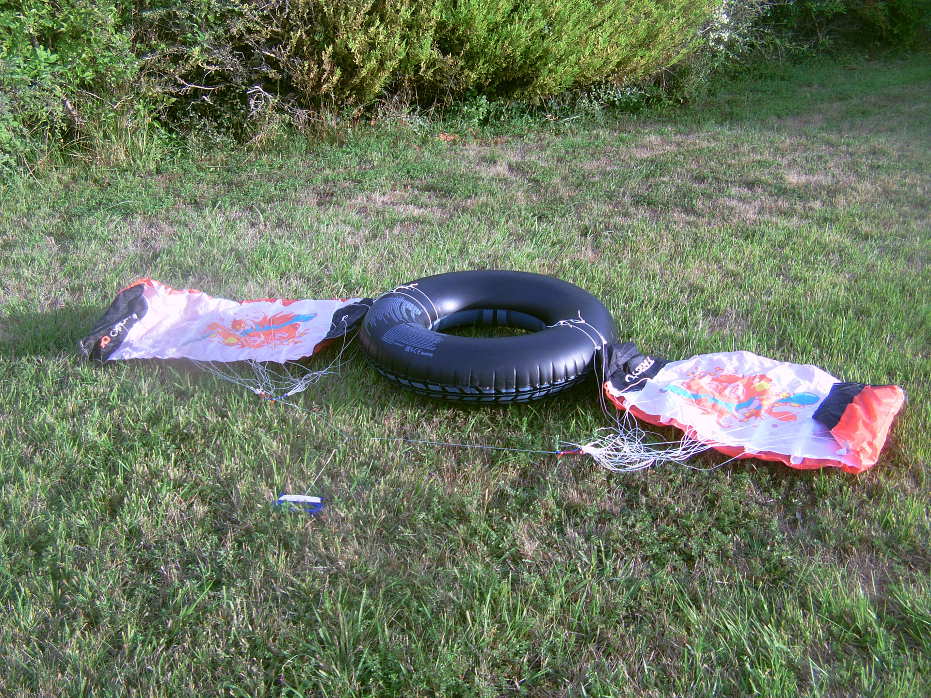
I am not sure at all. I just experimented a 36 cm diameter torus with two straight blades of 50 cm x 8 cm, and 41 cm out of the torus (see the photo below): the rotation was very fast with blind adjustments to the blade alignment, which was simply taped on. The previous slowing was due to the use of a 0.56 m diameter propeller whose swept area was truncated by the same torus.
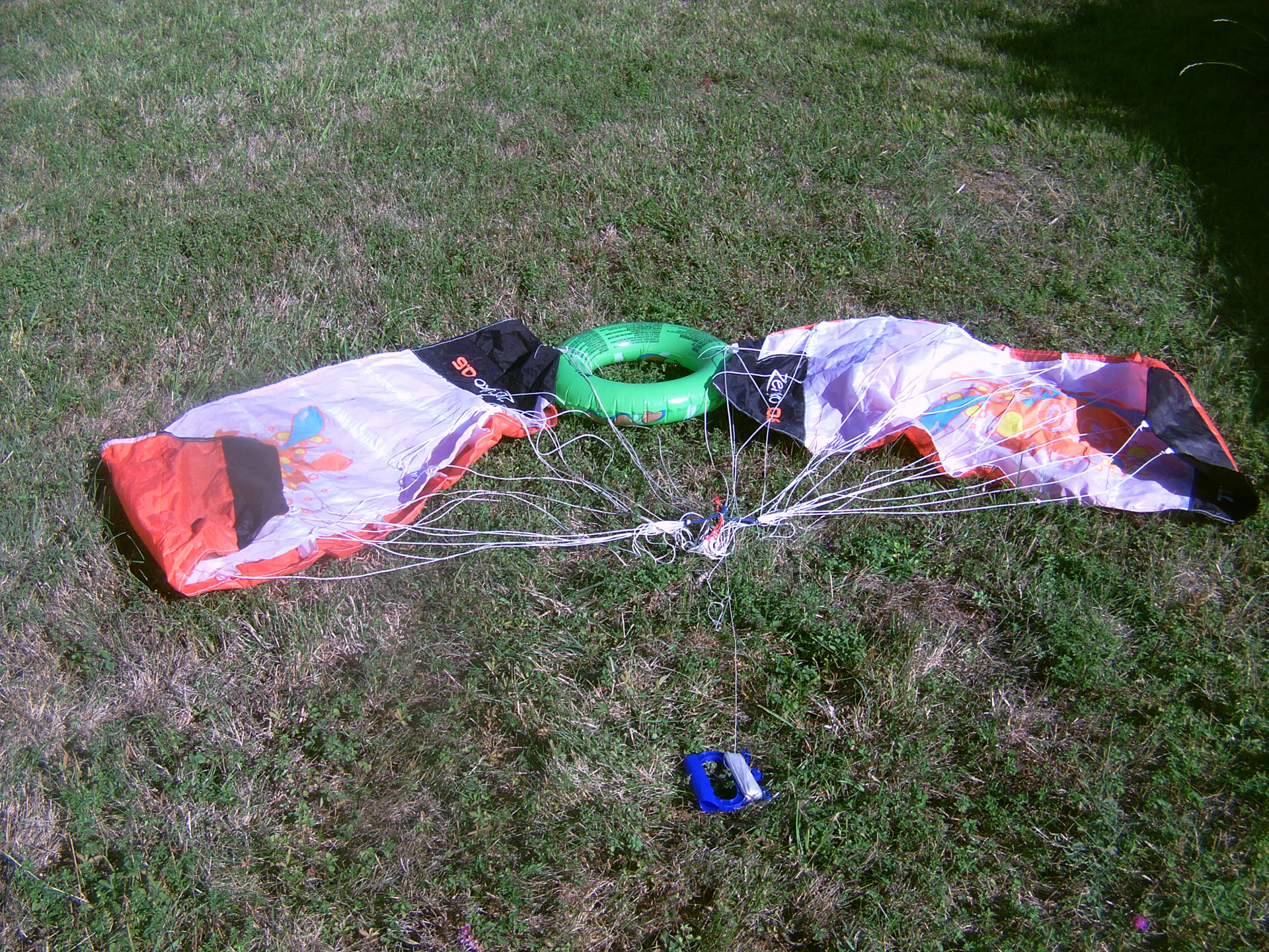
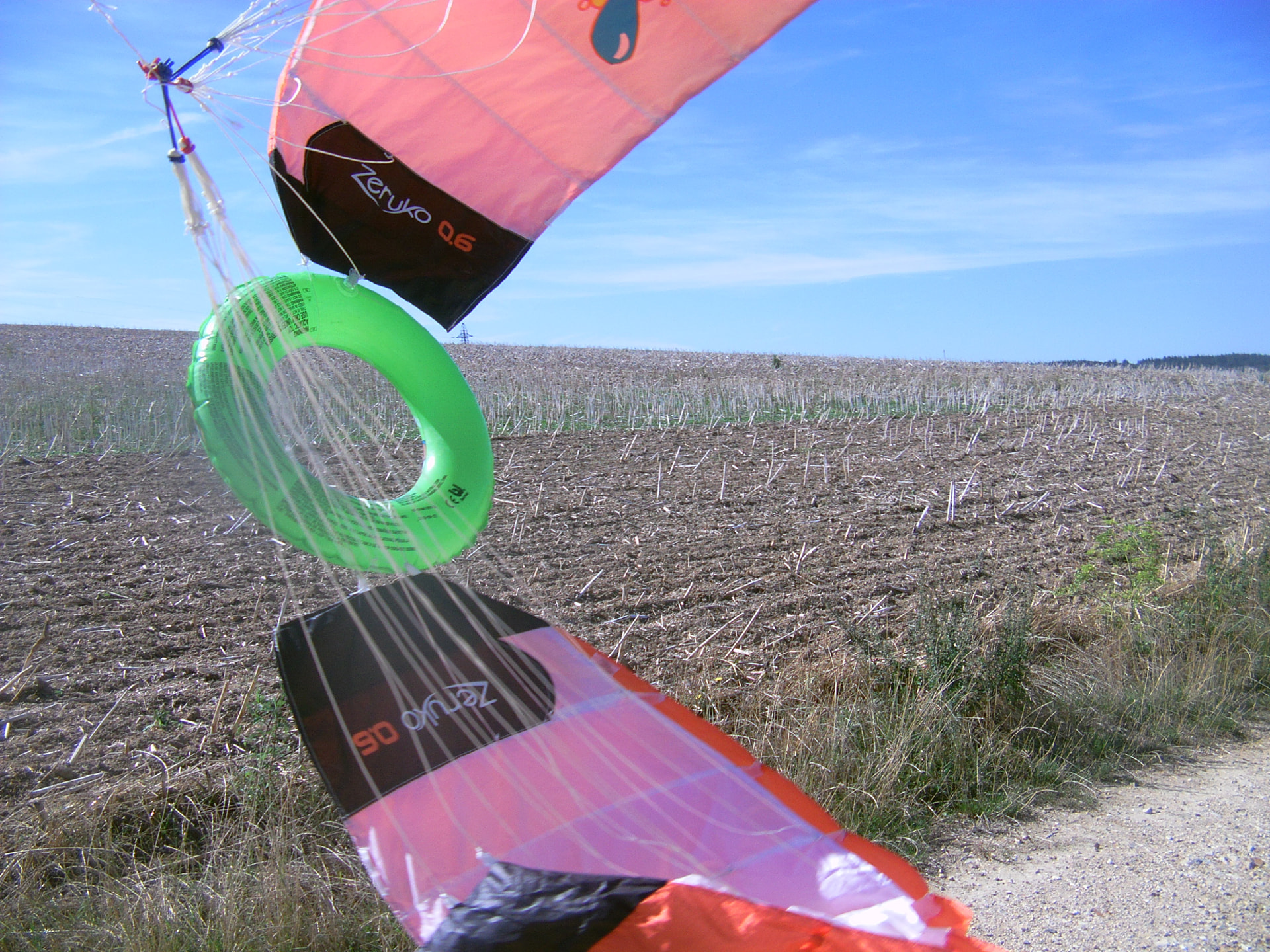
The ballute (torus) seems to simplify the construction and operation compared to a central parachute represented on photos et on a video. The torus adds a potential aerostatic lift when scaling up, and appears to offer a greater kite spacing than a sphere (which can be limited by the hoop stress issue for very large dimensions, because it depends on the diameter of the sphere), though this remains to be verified.
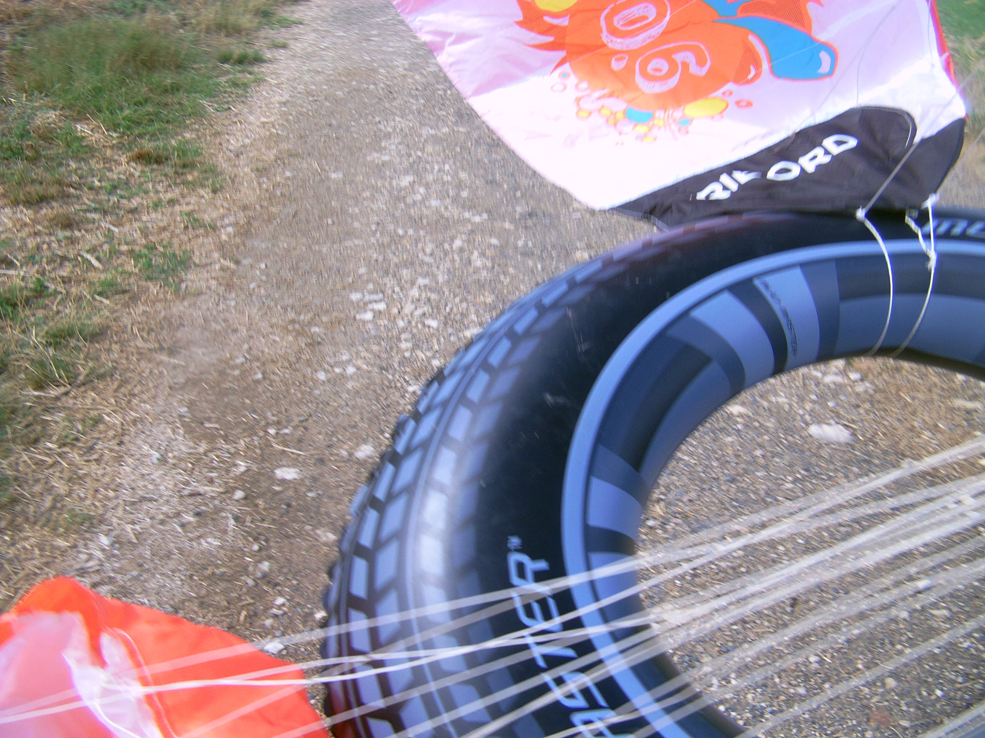
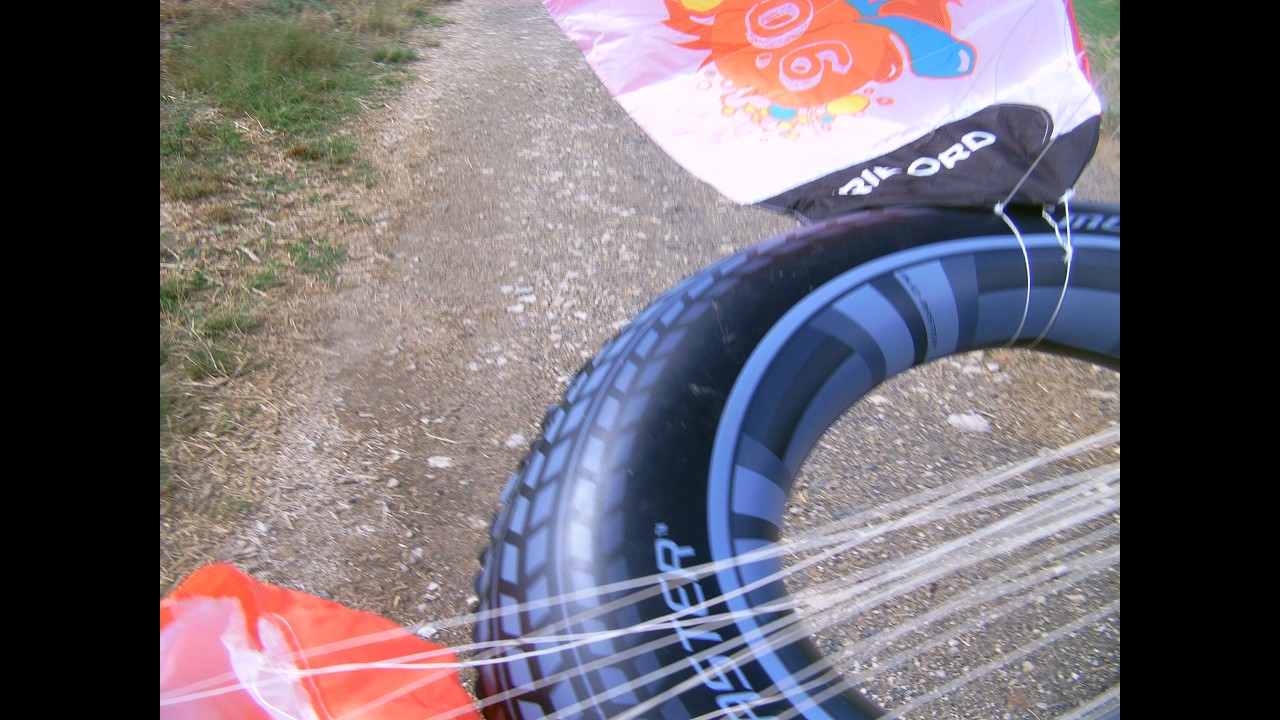
Experiments with a larger torus of 85 cm in diameter instead of 38 cm. No wind, so it is difficult to take conclusions.
Shown below is a larger torus installed amidst the same power kites. Testing is required to establish the right proportions between the ballute (torus) and the kites—factors that determine the kites’ speed and pull, as well as the aerostatic volume and the torus drag. Future research may focus on a very large torus [12 and 13] featuring kites or blades positioned both inside and out.
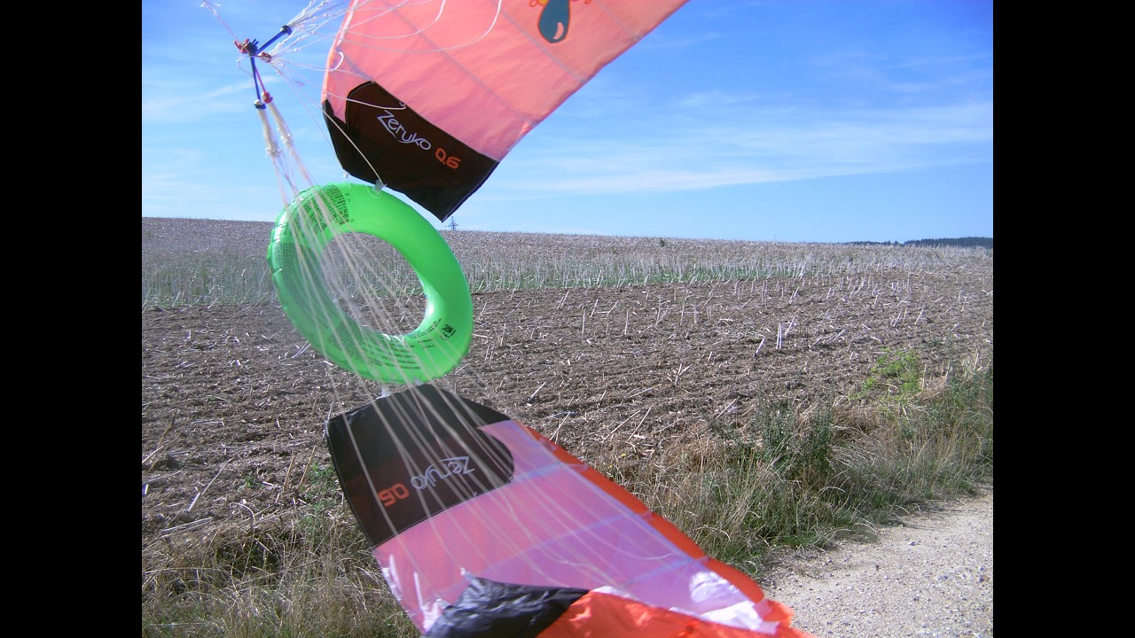
I made another short video using the same “big buoy” (85 cm), with a little better wind. Unfortunately, I hadn’t read your message yet. You can still position yourself behind the video to see the rotating mechanism turning clockwise.
Ultimately, a large, relatively thin torus—inflated with hydrogen shielded by a nitrogen layer, all contained within a double-torus structure—could suffice to support the outer and inner blades or an inner kite.
A torus could be based on a torus-type airship such like:
H. Suefuku, T. Hirayama, Y. Hirakawa, T.Takayama
From the introduction:
Nowadays, airships that were used in the past
are returning again and their use can be
expected in areas such as sightseeing, cargo
transportation, surveillance, disaster prevention
and rescue purpose. Left of Fig. 1 is a
conventional one (Zeppelin NT). Since the
conventional airship requires a large mooring
area and facility, landing and taking off from
arbitrary place especially from the center of a
city are difficult. Of course it is inconvenient
for airports far from cities . From this view
point, we have room to consider about the shape
and related system of airship resolving above
problem, other than conventional spindle type
airship. we have to discuss that if the most
effective shape is spindle or not.
In order to reduce the necessary area by
adopting a different shape and mooring system,
we propose the following new type of airship.
Our proposal is a Torus shape as the next
generation-type airship shown in Fig. 1(Right).
As the circular shape has an equi-directional
aerodynamic characteristics, its directional
control become more easier than conventional
ones.
Certain features could perhaps be adopted for AWES using tori—with the aim (whether achievable or not) of facilitating takeoff and landing through the possibility of vertical stacking, enabling further scaling (the torus bringing some rigidity with a lower sectional diameter than of sphere, so perhaps less hoop stress issue for a larger total diameter), and potentially benefiting from aerostatic lift, although inflation with air could be a possibility.

 )
)