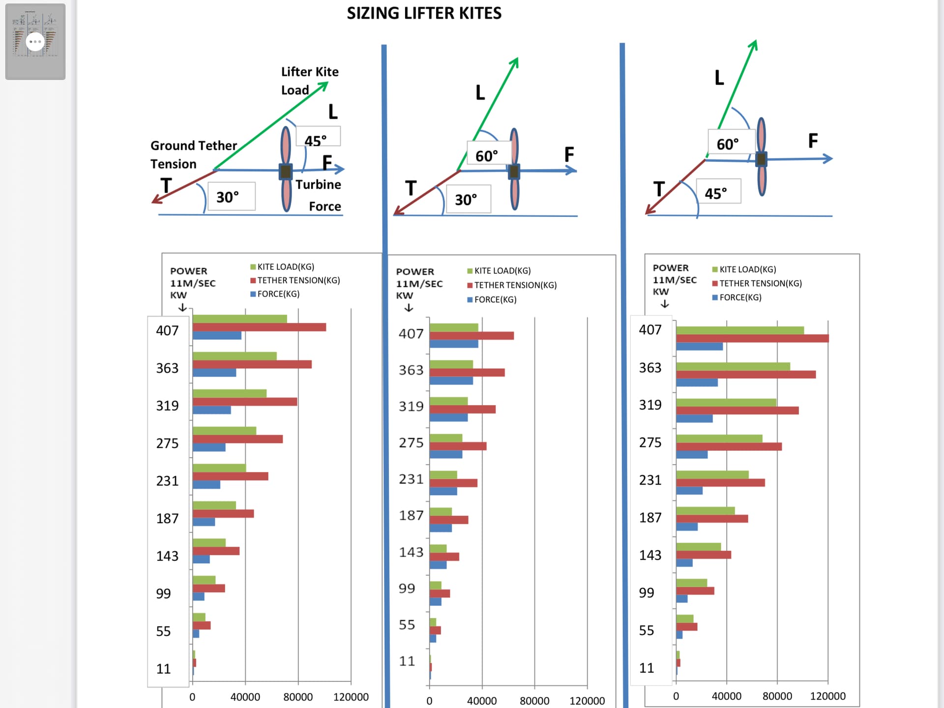
This analysis is for a Kitewinder style system where the turbines are oriented to face the wind. This analysis neglects the weight of the tethers, turbines, frame and transmission which are relatively small compared to turbine thrust and kite lifting force. The analysis shows that lower lifter loads are required for high lifter kite line angles. Unfortunately high kite angles reduces the kites lifting force so the kite size must be increased to account for this.
The analysis shows that larger ground tether angles will result in higher lifting loads and that ground tether angles above 30 deg will result in unacceptably large kite areas. In all cases, when the kite tether angle approaches the ground tether angle both the required kite tether force and the ground tether force become extremely large.
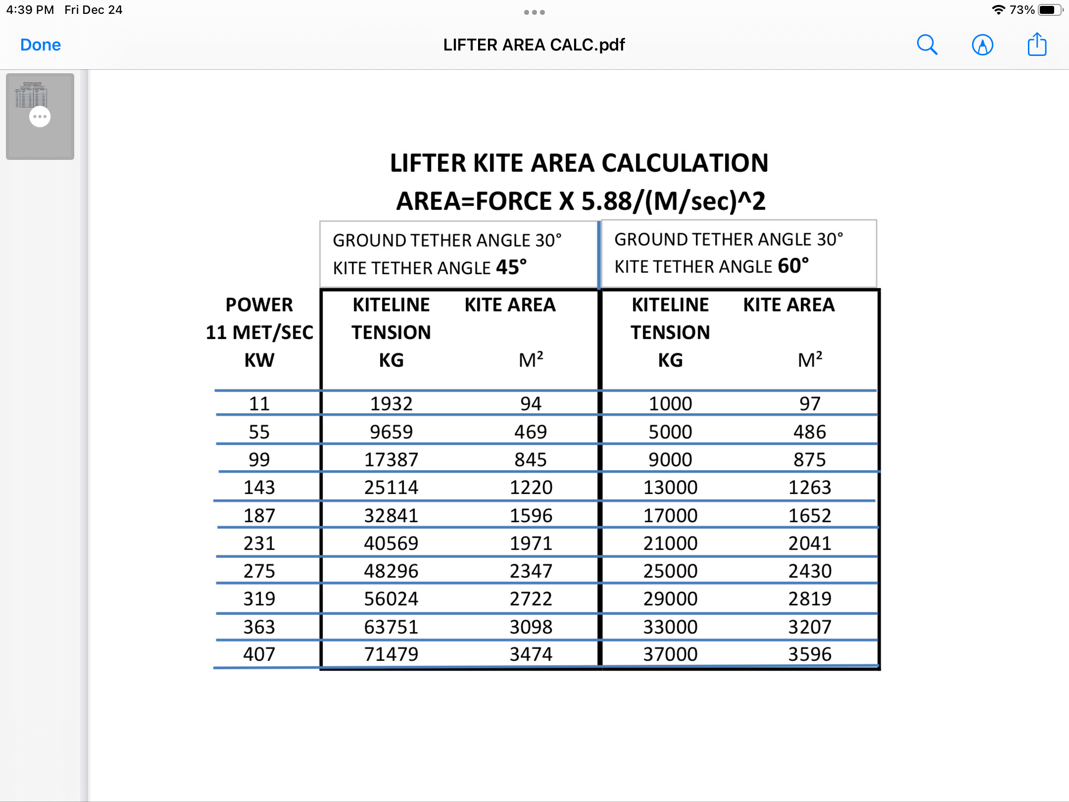
I have collected empirical data on tether tension as a function of kite area and wind speed. Unfortunately most of the data does not reveal the tether angle. We can assume that most lifter kites operate at 45-50 deg tether angle. If we assume that the tether tension varies with the square of the cosine of the kite tether angle, then the available tether force will be reduced by this factor as we go from 45 deg to 60 deg. ie cos260/cos245=0.5. The table below shows that when we increase the kiteline angle from 45 deg to 60 deg then using the cos2 rule the required kite area only increases by 3%. This is because lower required lifting forces due to high lifting angles counterbalances lower lifting forces caused by cos2 .
By playing around with the numbers, I determined that for a 30 deg ground tether angle the optimum kiteline angle is approximately 52 deg. This angle will require the minimum kite area. Increasing the ground tether angle will result in larger kite areas regardless of kiteline angle.
Analysis for Daisy, Superturbine(R), and MAR1 is more complicated since part of the lifting force is supplied by the angled turbines at the expense of power output.
May also be a way of eliminating some of the angles from being too Obtuse sat Down gave it some thought and came up with a design similar to an airport wind sock and a chandelier sideways on. Glorious Amur.stl (1.5 MB) granted its a work in progress. given the kind of things been considering. Basically using some of the old pioneering skills obtained while doing scouts and thinking about booms from ships. I don’t see why it couldn’t be gimballed to the side of a house. In the prevailing direction of the wind. I’ve used a visual mock mock of the Galileo generator to demonstrate. if it was completely polygonal like a annular wing and free to spin.what would happen when the winds pick up. It based on a wind sock you see at the airport so should be self aligning to the wind. The stl. file shows this in scale. @gordon_sp. There we go just an idea for the new year. While I think about it it probably do well up a mountain. Where there a lot of wind shear.
Indeed a stationary kite depends from Bernoulli’s principle (lift for short), as for a plane. So the angle of attack (AoA) prevails, and practically can vary from about 15 to 25 degrees, not far more.
In the other hand a crosswind kite undergoes cosine law in addition to benefit from Bernoulli’s principle, as for wind turbines where lifting blades also work crosswind.
Any kite will have maximum pulling force when flying close to the ground and will have almost zero pull directly overhead. I would be interested to know the pull of your kite when flying at 45 deg (adjust the bridling)?
Yes in crosswind flight, and no in stationary flight for a lifter kite. A stationary kite flying close to the ground would generate drag, not lift: it would be a parachute or a bol kite like on the video below:
Per m², pull (only drag) force can be a bit lower than the pull force (lift and drag) of a good lifter kite.
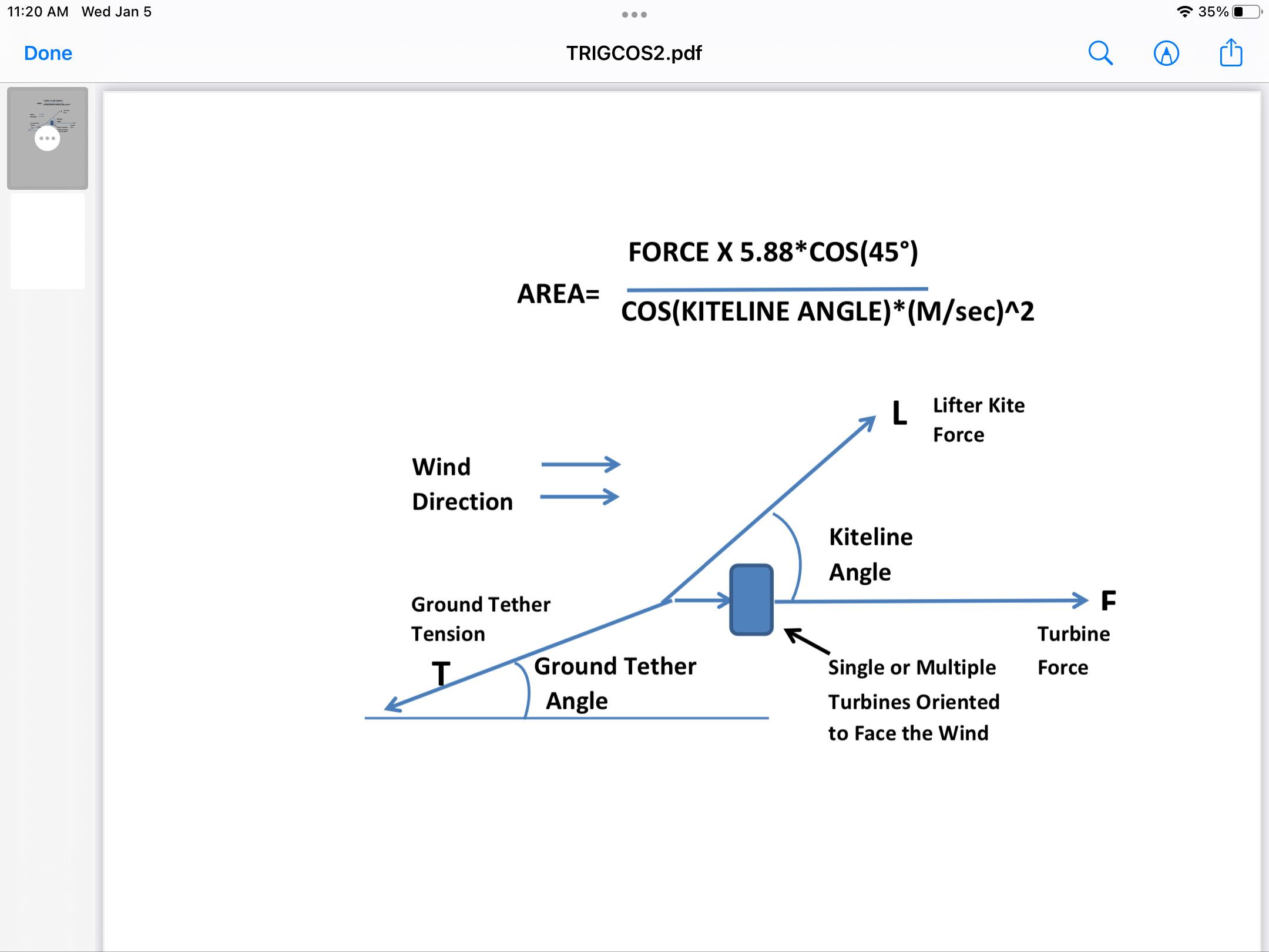
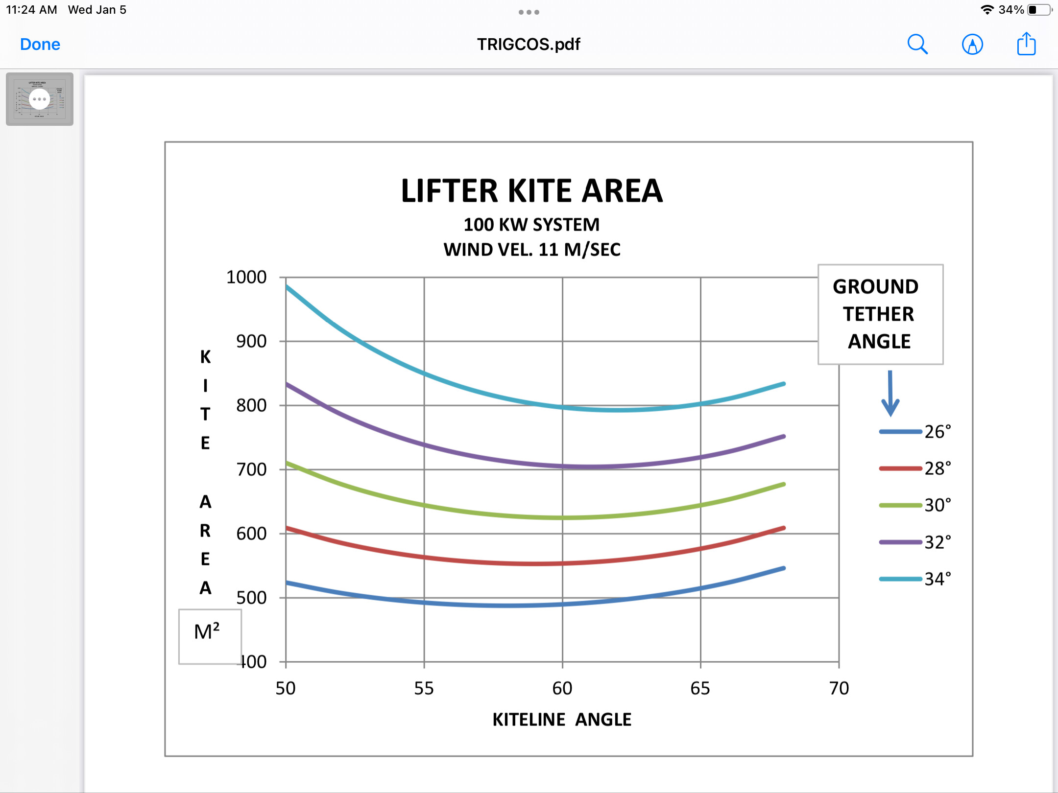
Since my previous analysis, I realized that kite tether tension should vary with the cosine of the angle of attack since the frontal area varies in this fashion. I therefore included this into my empirical formula. My analysis is for a 100KW system operating at a wind velocity of 11 m/sec. I calculated the kite area required for various ground tether and kiteline angles. The analysis shows:
1. Required kite area increases with increased ground tether angles.
2. Minimum kite area is obtained with kiteline angles between 55-65 deg. The lowest possible area is obtained with moderate kiteline angles and low ground tether angles.
The reason that there is a minimum area is because cosine losses become significant at high kiteline angles. This overrides the beneficial effect of operating at high kiteline angles.
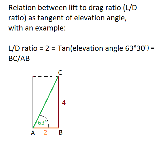
The ground tether angle is obtained by adding the drag of the turbine (roughly its swept area x air density x 0.5, if it is optimized, drag coefficient being roughly 1 or a little less) to the drag of the kite (the drag coefficient is approximately 0.3 or 0.4); then calculating the lift of the kite (the lift coefficient is approximately 1); then lift to drag ratio; then going to Tan(elevation angle).
The same for kiteline angle by removing turbine drag. A good lifter kite has a L/D ratio of 2.4, so an angle of elevation of 67°.
This is an affair of tangent, not cosine. I just corrected an old comment that was not based of the lift to drag ratio (L/D ratio) as tangent.
We subtract the weight (in N) of the turbine and the kite from the (kite) lift (also in N).
A similar calculation can be made for tilted turbines of the Daisy type with the lifter kite.
I think this analysis is flawed. A wing has some characteristics area, C_L and C_D that determine the elevation angle of the tether. As the kite is stationary its tether tension only is dependent on C_L and area and wind speed, unless you consider drag forces useful. Actually a high flying kite may gain more in lift force due to wind gradient than you gain by using drag force at a low elevation angle.
The kite will be bridled to produce close to maximum lift as defined by maximizing C_L. However you fly the kite you cant get more lift, only more drag.
The reason lifter kites fly low is mainly because of the difficulty of desiging a stable kite with a high glide number C_L / C_D.
It is a good move to determine the size of the kite lifter, and the graphics are good.
However, a static kite is not a wind turbine: a wind turbine (like a crosswind kite) sees its efficiency reduced when its orientation moves away from the flow, reducing the useful surface swept according to the cosine law, while a kite is subject to Bernoulli’s principle.
And the lift-to-drag ratio (L / D ratio) relates to the elevation angle, being the tangent.
Therefore, we have to forget about the cosine for all the analysis.
In a 3 year old comment, I made a big mistake using the cosine function when it is the tangent function as shown on the site with the graph I mentioned earlier. And nobody commented on this huge mistake that I made, and that you seem to reproduce (among other misconceptions), by not mentioning the tangent function once, only remaining (wrongly) on the cosine function. Results are very different. I noticed that at equal power and elevation angle, the size needed for a kite is about the same for Kiwee and for a tilted turbine like Daisy.
Below is a sketch:
Beside this, it is true that the mass of the turbine can be neglected, but only by high wind speed and at small scale. As the turbine mass undergoes cubic law by scaling, it is better to take this into account. It is not difficult: subtract its weight (in N) as well as the weight of the kite (in N) from the lift (also in N).
In order to size a lifter kite we must know what the tether tension is. The tether tension is the resultant of lift and drag and also depends on the tether angle. There is no easy way to measure lift and drag, let alone determining the value of lift and drag coefficients. (Do the coefficients change with changes in attack angle?) You can adjust the kiteline angle and the angle of attack by modifying the bridling of any kite. Clearly high kiteline angles will result in lower tether tension, and I believe maximum tether tension occurs at low kiteline angles. (Assuming the wind velocity is constant). Why don’t you conduct experiments on your high flying kite and see if this is correct? I have used an empirical formula to calculate the kiteline tension. I have assumed that all the data was obtained from kites flying at 45 deg. This means that the lift and drag forces are equal and that the kiteline tension is 1.414 X lift or drag. Is this correct?
For knowing lift to drag ratio (L/D ratio) it suffices to evaluate the angle of elevation. Tan(elevation angle) = L/D ratio. However, this does not give the absolute values of lift (L) or drag (D). For that you measure the pull with a steelyard and wind speed with an anemometer. Now you have the pull vector: so you can determine both lift and drag vectors then respective coefficients if you know the kite area.
Sure, I’ve had a good run with experiments and now have a cool little AWE system to charge your phone. We should have it available on Kickstarter in the next month. It’s so great to see everyone’s projects here, nice work! Here’s a montage of my wind experiments over the last 15 years. Clean Energy Projects - YouTube