Stall control of power in TRPT rigs

Many HAWT [horizontal axis wind turbines] are stall controlled. That is, when the windmill is overpowered, the are not speed up but instead retain more constant or slower rotational speed so that the angle of attack [AoA] increases and the blades stall. This in turn reduces power output. A simple and cheap scheme that does not require blade pitch control.

I was thinking, is this possible to transfer to a TRPT rig [torsional rotary power transfer, eg Rod Read’s Daisy]?

Well; a TRPT can only apply a certain amount of torque before the soft shaft collapses. This is usually the same torque that provides the maximum power output. But the max torque of the soft shaft may also be bigger than the optimum torque setting if the shaft is over-dimensioned, leading to possible feasibility of what I am about to describe.

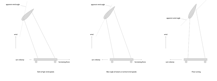
It does occur to me though, that it is possible to control the AoA through the harvesting force if each kite has two tethers connected at the front and back of the fuselage.

I have simplified the TRPT into a cart with a harvesting force to make explanation easier.

The starting point is adding a second tether to the kites of the TRPT so that it is pitch controlled. The length of the tethers may be fixed.

In nominal conditions, the TRPT should be running at optimal AoA [the center drawing].

If we brake down the TRPT by applying a larger harvesting force, the AoA of the kites increases, causing it to enter stall eventually. This may possibly be used in super high wind conditions to prevent runaway power output.

Also, if we speed up the cart by reducing or removing the harvesting force, the AoA will be reduced until the tether tension and thus the power output is very low.

I guess this is inevitably going to be a hard thing to stabilize control wise, but maybe not impossible.

There are some obvious variations on the theme where the length of the tethers may be adjusted by winches to control power output. Though this does not constitute the simplest possible system IMHO.

stall_trpt.pdf (19.2 KB)
1 Like

Understanding PID Control This video series makes it seem easy. Why would it be hard?

1 Like

Take it from myself as a control engineer by education. :slight_smile:

It is highly nonlinear and the controllability by “harvesting force” is very indirect. Power may be controlled both by increasing and decreasing harvesting force, depending on the state of the kite and the wind speed.

So I think it could be made stable for stable speed rotation quite easily by designing a simple controller for the harvesting force. But to make something to work in all conditions I think will be challenging.

Note: the harvesting force is probably applying torque on the generator at the hub of the TRPT. So that has a lot of flexibility and bandwidth. I guess the phase difference between kites and generator may be monitored quite accurately and cheaply, so that also gives hope for controlling it. This new technique adds a way to depower the TRPT in high winds.

3 Likes

I agree that this would be a strategy worth pursuing. Our hybrid turbine does in many ways fall in-between a classical wind turbine and a TRPT.

For us it’s been possible to achieve stall regulation using a speed control loop. In our case the mount of the generator is relatively flexible and that has caused a lot of control difficulties. Not so much the connection between the generator and the blades.

We also tried using softer blades (cord direction). That seemed to have some de-powering effect (say a factor 2-5 reduction in torque), but probably not enough to be really useful in high winds.

2 Likes

I must mention that this method mostly makes sense for «dumb» wings without their own control flaps.

1 Like

Cool @tallakt Another way to stall TRPT
Your cart in the drawing is effectively like the next lower ring in TRPT.
By running a pair of fore and aft bridles from (the cart) the next lower ring to the blade, As torsion increases (more twist per length) this pulls the rearward bridle more increasing AoA and stalling.
Elegant.

I can imagine there is potential for feedback and oscillation to become problematic with this solution.
Might be worth looking into whether reflex blade profiles could help to smooth out the responses?

Often wondered if a similar response could be made on the blade if they were mounted to the fuselage in a curved track. But working with inherently tensile design should scale better.

1 Like

Yeah I wanted to explain in the simplest way, that’s why I opted for the cart rather than a multi layer rotating TRPT rig. I hope everyone will be able to understand how it would apply to a rotating rig with braking moment rather than braking force and circular path for the kite.

Another thing that I am seeing now that I did not state as an assumption is that the kites are assumed to be pitch stable. So they would have either a reflex profile, spanwise twist, fuselage and elevator or something else. Changing the length of the tethers now is a matter of moving the attachment point forwards and aft. Probably the distance between the tethers should not be more than 1/4 chord I guess.

One can’t assume that the pitch angle can be set rigidly by the two tethers, because they will be curved due to tether drag, and thus act more as springs rather than stiff rods.

If the kites are not pitch stable they must be supported by a bridle that would stabilize them. And that bridle would have to allow trapezoidal motion as tether lengths change. I guess this would be quite similar to how any kitesurfing kite works today…

This is just the tip of the iceberg of the design space though. Thats why I mentioned that stabilizing these may be slightly difficult.

1 Like

Pitch stability is assisted by the way multiple blades can be set into fuselage cuffs. The fuselages are set on a rotor ring. The ring can already itself be fairly rigid, and by being in tension, the ring helps to align pitch of each blade with the aggregated plane of rotation.

You’re right that it needs as simple an explanation as possible.
I made it sound really complicated

Under these conditions it would perhaps be possible to adapt @someAWE_cb 's cyclic pitch control, by using it as stall control: Cyclic pitch control for Rotary Airborne Wind Energy Syst. using a rotation compensating slew plate.

2 Likes

A very interesting solution. As I had been thinking about anti stalling after reading the thread. I wonder if a compound wing tips would have made a difference? Much like winglet on the big aircraft are used to reduce drag. Could a compound wing tip make a difference? Reducing the need for complex mechanism. In some passive self stabilising system? Basically using the aerodynamics to your advantage. To always keep things centred. I’d worry the oscillation would lead to the kite destabilising during rotation. It just a thought. I wouldn’t know exactly where the cut off are or where the tolerance limits are? I’d reason that there would be. Question is one of size?

Somewhat related thread.

I think by the way the application of this is wider than just TRPT rigs, it seems you could do this also in some rotary MAWES and in HAWTs where you replace a part of the blades with these (which would make for easier testing of the idea).

1 Like

I thought so. As it a major part of the aerospace industry. Definitely something. I’ve encountered just never seen applied to turbine of any sort. Got me think tin can models. To test it out. Cheap easily available materials. Definitely worth a shot. I see if I can come up with something on with a cad model. For a rough idea.

I was commenting on the original post, not on your idea, in case you thought that.

I dont know exactly what you mean by a compound wingtip, but I believe the mechanical and awrodynamical options to arrive at a close to optimum design is well understood for those who know these things…

@Freeflying Perhaps describe with a few more words what you are thinking about so I can understand

In essence a compound wing, but at the tip of each blade. I know winglets are in common use on aircraft. I was thinking of the many way to go about this. Compound sections perpendicular to rotation. Basically at 90 degrees to the blade rotation. But still able to be in a crosswind. Or a set of winglets in compound formation in Along the aerofoil arc. Then have it in parallel with the blade. For the last part of the blades tip. I suspect it wouldn’t need all that much. The options being perpendicular. Or In parallel. A Compound wing form be that winglets or compound section. Definitely would have to play with the ratios. To limit unnecessary drag. The big problem for the big hawts I’ve seen is the amount of blade the have sticking out. One storm and may are broken beyond repair. If the tip could be made lighter sometimes but retain tensile strength. You might be on to a winner. I’m partly aware of the many man hours it took to get this far. Hence why was basing on some foundation stuff. Short blade = low Cog factor. Long blades = self destruction risk. Due to shear stress. vorsprung der technik and all that jazz. Hopefully like to draw something up. To show some point this week.

I just leave this here as a demonstration The IMPOSSIBLE is now POSSIBLE | Fan Showdown S3E6 - YouTube should give you an idea of what I’m thinking about.
Compound winglets.stl (109.2 KB)
Tip b.stl (65.0 KB)
Wing 1.stl (44.1 KB)
A morning work but you should get the idea.

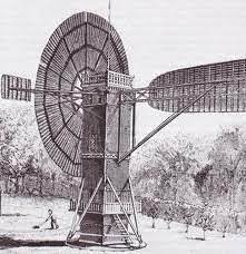
Wow, 13 years into the current hype cycle and someone finally notices how early wind turbines worked. Of course we then immediately transition to how complicated we can make something so simple.

2 Likes

I think many of us know some basics about HAWT design. Though I am sure i [we] could always benefit from more knowledge. Alas, having all knowledge is not possible so we all must get by with what we have.

Wrt the original post, i think it is not directly comparable to a simple HAWT because having it being a rotary AWE makes some things a bit different. And I have so far not seen a similar idea shared… but I admit its not rocket science

@dougselsam @tallakt
it that old saying of K.I.S.S, most engineerings should be familiar with. It is indeed strange to see the tangent engineering will go off into. From humble beginnings grow them mighty oaks. It is also very true that with knowledge bases you need to know to be in touch with the design profile. Many do make do. But if there’s enough of a clue there definitely something to be explored. Fantastic, it good to know your origins. A picture for visual. It hadn’t occurred to me till it was mentioned. Wind is one of the oldest power sources. Seen widespread use. Great stuff.
image

Hi Tallak
I’m not finding fault with your mentioning stall control. It’s just that I’ve spent 13 years telling people that overspeed control is “not the main thing, it’s the only thing” in wind energy (just making power is the easy part), and never had any meaningful comment back on the topic, except people ignoring what I say, resisting it, or coming up with the common, predictable response of “we’ll just shut it down if strong winds are forecast” which would mean giving up your most productive operation. Stall control machines were developed by the “farmer with a welder” people in Denmark, and is +sometimes called “The Danish Concept”.