They may not have the means to buy a ship to move the anchors.
In ferry boat example the anchors are fixed. They can travel to a channel and watch, at low cost.
Payne and Culp were gifted marine engineers. No such expert would doubt anchor shifting is a proven method.
They may not have the means to buy a channel with a ferry boat to move the anchors.
We at least agree how incapable those players seem. USP3987987fig5 is only for those who can make it work.
I do not agree. AWEurope venture is a fine organization, and take care of what is workable.
You think AWEurpope’s circle can’t even afford to test anchor shifting, or even just reason from the existence proofs.
Its still the Makani/Ampyx/TUDelft axis behind AWEC, the failed California 501c4 predecessor. That’s not a high standard.
Makani/Ampyx/TUDelft is a high standard in AWE. They would not buy a crane or a ship to move anchors.
Let’s agree AWEurope leaders are not intending to buy into anchor-shifting AWES concepts based on USP3987987fig5.
Fraunhofer is the true high standard in EU AWE engineering R&D. AWEurope does not compare well, by any serious measure.
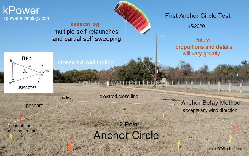
The Tri-tether is the 3D extension of USP3987987fig5, starting as a 2D plane defined by two crosswind anchors. I arrived at the Tri-tether, thanks to USP3987987fig5.
The Tri-tether avoids anchor-shifting (anchor belay), if wanted. Its ok if AWEurope cannot afford to research these methods, kPower does.
The key inventive leap in these powerful crosswind schemes is to use Earth itself as a dynamic anchor-field. Multiple-point anchors are cheap compared to previous schemes that required carousels or tracks for similar gains.
Again this conspiracy thing. Man you are weird! Well anyway. So you perform a test. I saw a video. Looks like really unstable. So what were the results? Why not try producing electricity and quantified it? A power meter is 8 euros on Amazon
It looks like some possible progress.
Some observations and questions, then a suggestion:
As the “future proportions and details vary greatly”, the diameter of the Anchor Circle should be (about 10 times) far larger compared to the kite size, that in order to allow the kite making fast and long crosswind trajectories and sweep more.
The FIG. 5 part seems to be within the installation, going from the two pulleys toward the kite, the pendants and the Anchor Circle being the added parts.
So the two pulleys look to be on the ground, not in flight, is it right? Are they anchored on the ground? If yes you have to move the two (FIG. 5) pulleys when the wind direction changes, while in the same time
you should detach the pendants from the anchors to reattach them to the two appropriate anchors. How is it possible without human intervention?
Suggestion: removing pendants then settling the (FIG. 5) two pulleys directly on the two anchors, installing a circle line connecting all the anchors. When the wind direction changes, the (FIG. 5) two pulleys slide through the circle line, from two anchors towards the next two anchors. Each anchor would comprise a mechanism to retain then release a pulley, leading to a possible automation.
I like the idea of including a crane in our designs…
The one highlighted above looked too wobbly and wouldn’t work well as a kite handler for launch and land assist.
Think of the energy vault system.
It has a lot more capacity for anchoring the crane ends to the ground, and making them good as kite tether working points… All those wider out blocks could be handy for
Adding more rails on the same beams for kite handling might help.
I posted some very basic ground anchor circle ideas on youtube some years back… The sound will no doubt be awful and the voice boring… Just look at the pictures
Just looked at that old video… what a lot o plop I drew… The wee rope riding wheels are the wrong shape and have to be on stub axles to allow the carriage to ride over patches
Problem with USP3987987fig5 though
is you want those pulleys at the side to be really wide for long stroke so as to avoid reciprocation in the whel direction. Not sure a crane in the middle can service that.
Its uncertain just what happened to AWEC, the insiders have never disclosed the process. Olivier may be right to suggest it was a “conspiracy”, but until the actual facts are public, that’s just one guess.
The latest experiment was not for measuring power, only for operational research. John Borsheim. PE, made kPower’s first AWES power meter in 2008. There is little value in a single data point in low wind, what counts is full power curves later. Due to low wind and no load, this was a <10W class performance by the 1.8m2 wing, mostly just to fly and lift the lines.
Its a wild leap from seeing cranes as one of a long list of load-connection models to thinking we need them on a kite field. The experiment was aimed at showing how little hardware is needed. Alpinists do not need a crane to climb mountains by anchor belay.
The rig shown by the Figure 5 and some variants might not fully use the pulling force of the crosswind kite, which would decrease the potential compared to the (yoyo, reeling) pumping mode.
Its going to a matter of testing Fig5 configurations against reeling AWES, testing-diligence none of the reeling players are interested in. Its not enough that only kPower has tested Fig5 prototypes and makes its claims accordingly.
Fig5 favors the power kite most of all, by eliminating the upwind cycle. Reeling favors the kiteplane that can glide quickly upwind. Its a complex “soft vs rigid” contest.
How does it work in automatic mode?
There are many variations proposed. For example, massive autonomous anchor vehicles that move as needed, or cars on tracks.
To me, the most wonderful option is to be on a pioneering kitefarm pilot team, and get out there and belay giant loads like industrial workers do, while automation eventually catches up. Imagine “manual” sailing in the sky, on an epic scale. That’s a better job than automation programming.
So apparently there is no mean to make the anchor belay medium to work in an automatic mode as I asked. And cars on tracks lead to an expensive and complex carousel.
No Pierre, there are already massive mining vehicles with autonomous-driving modes. Its true that rail-tracks and carousels are capital intensive, but they are readily automated too.
Again, the tri-tether is Fig5 in 3D, and eliminates belay while accepting wind from any direction.
As a temporary conclusion of this topic, and spite of my initially rather favorable opinion about the studied system, some bottlenecks occur such like the pulling force that is not well oriented or the added devices to allow facing the wind directions. And the implementation is rather complex compared to the pumping mode. So building them looks unlikely.
Again, we must add the cosine concern to the aforementioned problems What is possible with Payne's patent US3987987 figure 5? - #10 by PierreB .