Yeah
Very disappointing
It’s a combination of several issues
We did expect more from the 8m that’s definitely 1 issue.
We did know static kite supported kite turbines would meet a limit soon - Not this soon.
We didn’t expect the turbine and TRPT mass to be so high. (We needed to test single rotors - had been predicting to be working with multi stacks)
Other reasons the project had to stop was that we were all in different locations, reworking a solution in order that it could be demonstrated as a nearly marketable device ASAP, on a small budget with huge administrative overheads.
And yeah we wanted it to be safe.
We didn’t have resources to rework such a major component of the design.
Gutted but still trying.
Going back to the designing, the garage builds and technical aspect tests, will help remove the chance that I faced the Peter Principle - (e.g. Getting promoted to the level of my incompetency)
Things I’m OK with that I’ve learned I’m personally shite at -
understanding accountant language,
not being an aerodynamicist,
coordinating cloud based documentation for multi agency reporting on every shinny looking platform on flimsy copper broadband…
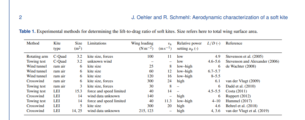
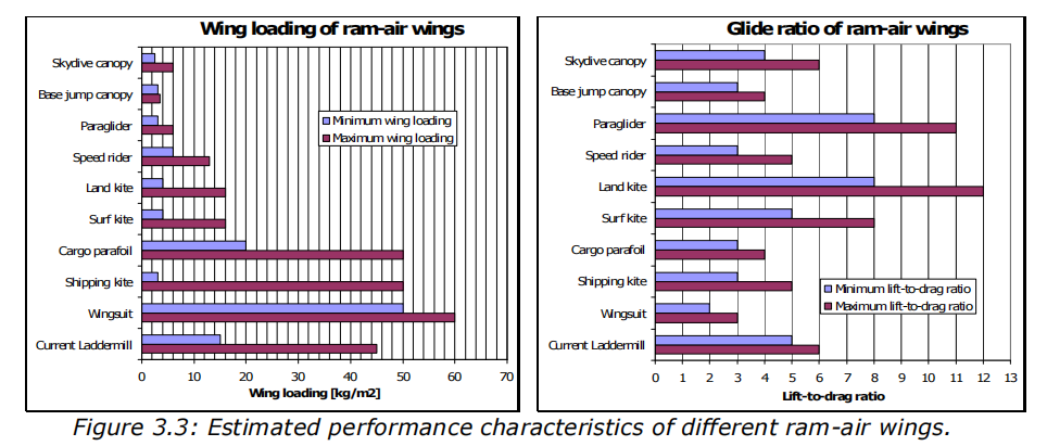
I would expect the LD ratio to be in range 3-6. I think the source you found is quite good.
Generally if we just look at the lift I would start by using a Lift Coefficient of 1 for basic calculations. Unless you have a multi element airfoil it’s will be very hard to get above 1 consistently.
Our wind turbine airfoil generally operate at less than 1.
Last year we (Mostly Lara T) ran another Life Cycle Analysis on a proposed 50kW Kite Turbine
The headline
Total Emissions per kWh generated [g CO2e/kWh] 0.78
From the summary headlines
Electricity Generation Parameters
Overall Device Emissions
Parameter
Value
Notes and Assumptions
Lifecycle Stage
Carbon Contribution [kg CO2e]
Device Rating [kW]
50
Raw materials
2,004
Windswept Capacity Factor
0.528
Taken from paper ‘Life-Cycle Assessment of a Multi-Megawatt Airborne Wind Energy System’
Manufacturing Processes
27
Device lifetime [years]
20
Based on typical design life for conventional wind turbine
Transportation
188
Total units of electricity generated over device lifetime [kWh]
I reckon Chinese progress on renewables deployments means the forecast figures we used for their grid CO2 intensity will likely now be superseded.
For some of you, these documents reveal the scale of market penetration ambition Windswept had last year - And this may be a wake up.
Was it phase difference between compressive elements that you have to control to prevent shaft collapse, and distance between compressive elements doesn’t matter for that as long as you control phase difference?
And what is the maximum or the desirable phase difference?
From the design reasoning report on page 26:
Due to the geometry of the TRPT, a 7N inward force results in a 12N compressive force.
How is that calculated? And between rotors you would have to counteract the compressive force, not the inward force, with outward lift from a bank angle and centrifugal force?
As part of the geometry ratio for TRPT sections (distance:radius) … “Distance between the compressive elements” affects the torsional rigidity and rotation lag for a given force ratio (tension:torque)
So it is a very important factor in the design of a system where you can expect a set of operational and peak loads.
Lag (rotational position) control is one way you can control to keep the compressive load within safe working limits
Each beam is getting compressed from both ends with a line (force vector)
Peak and transient loads were going to be a bit too much of an unknown to risk making a product at this stage
Right, that was a bit of confused thinking and question. A 100 meter section with 10 compressive elements should roughly have the same torsional rigidity as a 10 meter section with 10 compressive elements, was my question, but that feels self-evident now. …but then using twist feels wrong, since that 100 meter section would be twisted less than the 10 meter section – or maybe the same but over a longer length. Phase difference, lag if you never drive the kites from the ground station, or similar would be better.
Page 26 again:
Windswept - 10kW Prototype Kite Turbine - Design Reasoning Report
During rated operation the expected force on the tether wires is about (9000N/5) 1800N and the torque on the entire TRPT is about 1200Nm. Under these conditions the TRPT is only expected to twist 3 degrees per section, with an almost negligible inward force of 7N.
In transients however, this inward force can increase significantly and quickly. With a 30 degree twist the inward force goes up to 625N and right before crushing (60 degrees) the force even increases up to 2600N. It can be seen that the TRPT needs to be designed with great safety margins in mind.
That is only because you don’t reduce the regenerative braking fast enough? Can you not react instantly (10-100ms, or at least much faster than the rotor acceleration in gusts), or use something like a PID controller to keep twist in a band? Since you are using a motor you could perhaps use it to mitigate any rotational inertia in the ground system.
Due to the geometry of the TRPT, a 7N inward force results in a 12N compressive force.
This is confusingly stated to me, as the compressive force you talk about here is Euler’s critical load or buckling load on the tubes in the rings, not the torque compressing the shaft, which I gather is just your inward force?
Yeah fully depending on the controller you specify and whether you’re working all 4 quadrants
regen and drive forwards and backwards
2 really because ideally we only ever go clockwise
However the latest 40kW class VESC wasn’t out when we designed our plans for control VESC STR-500 100V 500A gorgeous
We were going for as fully simple a system as possible
regen only
(no overwinding recovery - bit of a step back)
and not trying to operate a lag control because silicon IMU’s are unreliable (we could have gone smart with 5 and averaging etc but time), Ring laser IMU’s are expensive and Magnetometers are iffy at best,…
We were proposing to run from a line tension based regen control (we’ve done it before) but there’s always a chance to mess up and with the inertia in the rotor and the potential full braking we had… didn’t look trustworthy
About the VESC. These are built for skateboards first and foremost. I have some experience that these are not optimal for flying things
Overcurrent causes the VESC to trip. Its not possible to foresee this. I could just happen. If you disable this, the VESC will give out that yummy blue smoke.
Better behavior for a flying object is to keep flying at reduced performance. At least then you have a fighting chance.
I am not sure though what that chinese VFD does on overcurrent. Probably something undesirable. Also its anyways not suited for anything airborne
For many AWE applications, i think the IMU is the wrong choice because it is made eg. for a car or a plane. Rotating wind turbines would have severe G forces and not a lot of opportunity to figure out what is up or down.
The electronics though handle rotating fine. I propose rather just make a simplified IMU looking at gyro and accel to estimate the phase and rotary speed of your kites. This should work well. Also please use five redundant units, the chip is so cheap it is being included on many boards «free of charge».
You are right Tallak
I should trust silicone IMU’s more in my kite.
I trust my life to them every time I ride my electric unicycle
And maybe I should wear some more safety gear
I was thinking you could get the angle of the plane of rotation of the kites from the IMU data (and from that determine elevation angle). If that is right, you could then tell your control software to stay within some plane of rotation angle. Or let the kites follow the path of the circle you want, in the correct orientation that it would have on the surface of the imaginary sphere the end of the tether makes, but ignoring the location of the circle. You’d slowly change the orientation of the circle, and its location would slowly change with it, would be the idea.
But I misremembered and thought you said it was the GPS that could not handle the g-forces, or maybe I read that somewhere else, so the idea above would avoid that.
Just place the imu in the centre of rotation of the rotor.
If you’re really worried about rpm being excessive (not going to be) you could use a laser ring IMU. Very high end fancy kit