A little off topic but i have heard that combustion stability is a big issue when you scale up rocket engines to much. That is why the Soviet moon rockets had many small motors while the giant Saturn V’s F-1 engine had some internal baffles in the combustion chamber to try to stabilize the combustion in the big combustion chamber.
On the Space-X side i am guessing production and modularity is the biggest factor in going for smaller motors in greater quantity. And you also get more redundancy and safety factor, and more trust vectoring control options.
I try to refocus on this topic because it is interesting. Indeed at present the only AWES marketed (https://kitewinder.fr/) implements a rope drive transmission. If this system is scalable (and I think it can be) it can lead to some good surprises.
So reading the figure 1 of the patent below can be a start for ideas to scale:
For the study to be successful, said figure 1 needs to be compared to Kitewinder’s patent below as it intends to solve some transmission issues:
Hi Pierre
Well, aside from what was later called “laddermill” being the first wind energy innovation that popped into my feeble brain as a teenager in the 1970’s (hard to believe nobody has even tried to build one yet), I haven’t heard much about kitewinder lately and am curious as to how that effort is going.
Most of Goldstein’s schemes will not work due to the fact that there will be insufficient tension in the cable drive to operate. This is especially true in the case where he uses an auxiliary tether where the load is split between the tether and the belt drive. During operation, if the tension in the return side of the cable drive drops to zero, then the cable can wrap around the drive wheel and/or the cable can wind up on the drive wheel, rendering the system inoperable. If the axis of the turbine is parallel with the tether, (same elevation angle), then the force of the wind will tend to drive the turbine towards the ground. To counteract this we must tilt the turbine upward, further increasing the cosine cubed losses. In contrast to this, the Kitewinder system orients the turbine to face the wind and employs a lifter kite to increase cable drive tension and prevent the turbine from being driven towards the ground.
Unlike the Kitewinder system, which has a floating generator, I recommend the use of a vertical axis generator which can be permanently fixed to the ground. I feel that this I necessary if we want to scale up to a permanent installation. We require idler pulleys both at the turbine(s) and at the ground generator to reorient the cable direction. Bottom Idlers should be located close to the drive wheel since the sag of the cable would result in premature wear on the cable due to rubbing on the walls of the pulley, especially on the low tension side. Changes in wind direction can be accommodated by rotating the bottom idler pulleys in a circle around the generator pulley. It may be necessary to rapidly rewind the system due to low wind speed, turbulence or turbine malfunction. In order to do this we can surround the drive with a vertical cylindrical windup cage which can be independently powered to operate at high speed. The cage diameter can be much larger than the generator pulley. In order to minimize rewind forces, we can orient the kite to fly directly overhead during the rewind procedure. The concept is shown in the attached drawing:
While vertical-axis motors and generators obviously do exist, there is an advantage to a horizontal-axis configuration, at least as far as my understanding: I believe bearing loading is simpler for a horizontal shaft. All you need is two simple ball bearings to cradle the shaft. Each bearing supports half the weight. This may be more important as size (weight) increases. One might notice how common the horizontal-axis configuration is. When you picture a motor in your head, it is usually horizontal-axis.
Vertical-axis motors and generators require thrust bearings to support the weight of the rotor. Not sure how often the weight is supported equally between an upper and lower bearing, but regular ball-bearings would be a problem especially for the lower bearing. One might get away with a V-A configuration for a period of time but then bearing wear might set in.
However, I have seen the giant generators at Niagara Falls - well, 50 years ago. They were huge and vertical-axis. So it is certainly possible.
The generators we manufacture use special bearings that allow any orientation, but I am pretty sure that for ultimate longevity and cost-effectiveness, horizontal shaft motors and generators are most common for a reason.
I think that the situation is different in the case of a cable drive. Changes in wind direction require reorienting the pulley, shaft and generator to face the wind. This is difficult for large installations. In contrast, movement of the idler pulleys is simple.
Certainly a vertical shaft is known and possible, no question. I was just sharing an observation I had made a while back, regarding the simplicity of the bearing support for a horizontal shaft generator.
I would point out that the uneven tension between the two sides of a cable drive might tend to cause an offset aim to an idler assembly, either on the ground, or up in the air. (?)
I would assume (as someone who knows little about constructing HAWTs) that a significant portion of blade lift is facing downwind, and a thrust bearing woud be necessary to counteract that.
Doug, @gordon_sp hopes the download of his pdf document has worked!
Furthermore Gordon describes a vertical axis generator, not a VAWT as such. So the constraints are not the same. There is no rotor just above the described vertical axis generator. However the quote below suggests the opposite:
Indeed with a rope drive we have some “uneven tension” but it is negligible.
The advantage of permanent vertical axis generator by all wind directions remains.
Yes the thrust loading of the spinning rotor is a factor that can’t be ignored. It can be pretty strong. Also, many turbines tilt the rotor up a bit to avoid tower-strikes, which slants the shaft downhill to the downwind direction, adding to that sideways force on the bearings. At least in the “small-wind” turbine world, most models just use regular ball-bearings, which are not really meant to take much thrust loading, but they get away with it. Some of my tower-mounted SuperTurbines tilt upward so the downhill gravity thrust is counter to the wind thrust force.
One example of a vertical-shaft bearing problem is the oil-impregnated bronze bushings that the furling tails are mounted on can wear away after several years of operation. I’m rebuilding a 10-kW machine right now where there is almost nothing left of the bushings supporting the tail.
Why not use a horizontal driven pulley, supported on either end, and have the idler pulleys above the pulley? You can still then have you winding cage if you like I think.
Also you say in your configuration the idler pulleys are there to remove slack. I don’t see how that would work. They only have very limited travel to deal with any slack and if they do travel (down) they become misaligned with the driven pulley.
Beside the interesting study from @gordon_sp, the problem I see is the requirement of devices such like angle pulleys in order to assure a correct transmission from the tilted propeller of type HAWT. The more it scales the more weight penalty occurs. Moreover a farm of these devices would be difficult to manage due to the risk of collision with serious damage.
So the rope-drive can perhaps be more suitable for horizontal VAWT because it naturally assures both tension and transmission without supplementary devices. Moreover a farm of horizontal VAWT can be more easily managed, the possible collisions leading to minor consequences, as for AWES farm in bumper car mode.
Darrieus, Savonius (like for the design) and other horizontal VAWT could be used. In all cases the lower efficiency by unity could be compensated with both a higher use of the space and a simpler rope-drive transmission system.
The bottom idler pulley redirects the cable to the power sheave. We are not trying to remove slack in most of the tether. We must remove the sag in the short distance between the idler pulley and the power sheave so that the tether does not rub against the wall of the sheave. If the idler pulley is located a few centimeters away from the power sheave, then there will be almost no sag.
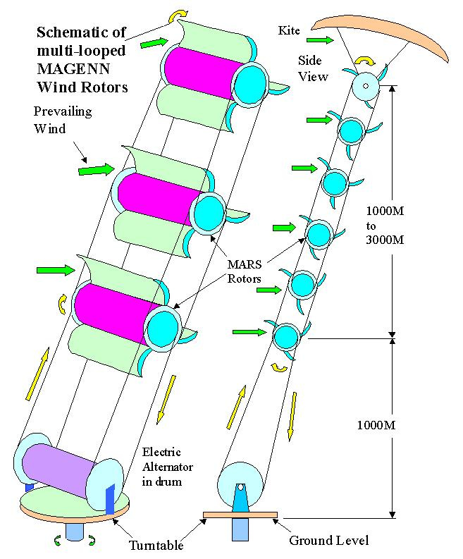
Interesting, nice graphic, and it “works great” as long as it remains “on paper”. Savonius… something beginners can understand…
Level after level of loops: what could possibly go wrong? Ever had your chain come loose on your bike? And that is a fixed geometry, not floating in the sky, where everything could come loose in a downdraft.
This would appear to be a watered-down version of the old concept from the 1970’s, more recently renamed as “Laddermill”, which had already conceptually transitioned to SuperTurbine™ by the 1980’s. As in, this idea would naturally lead to laddermill, which leads to SuperTurbine™.
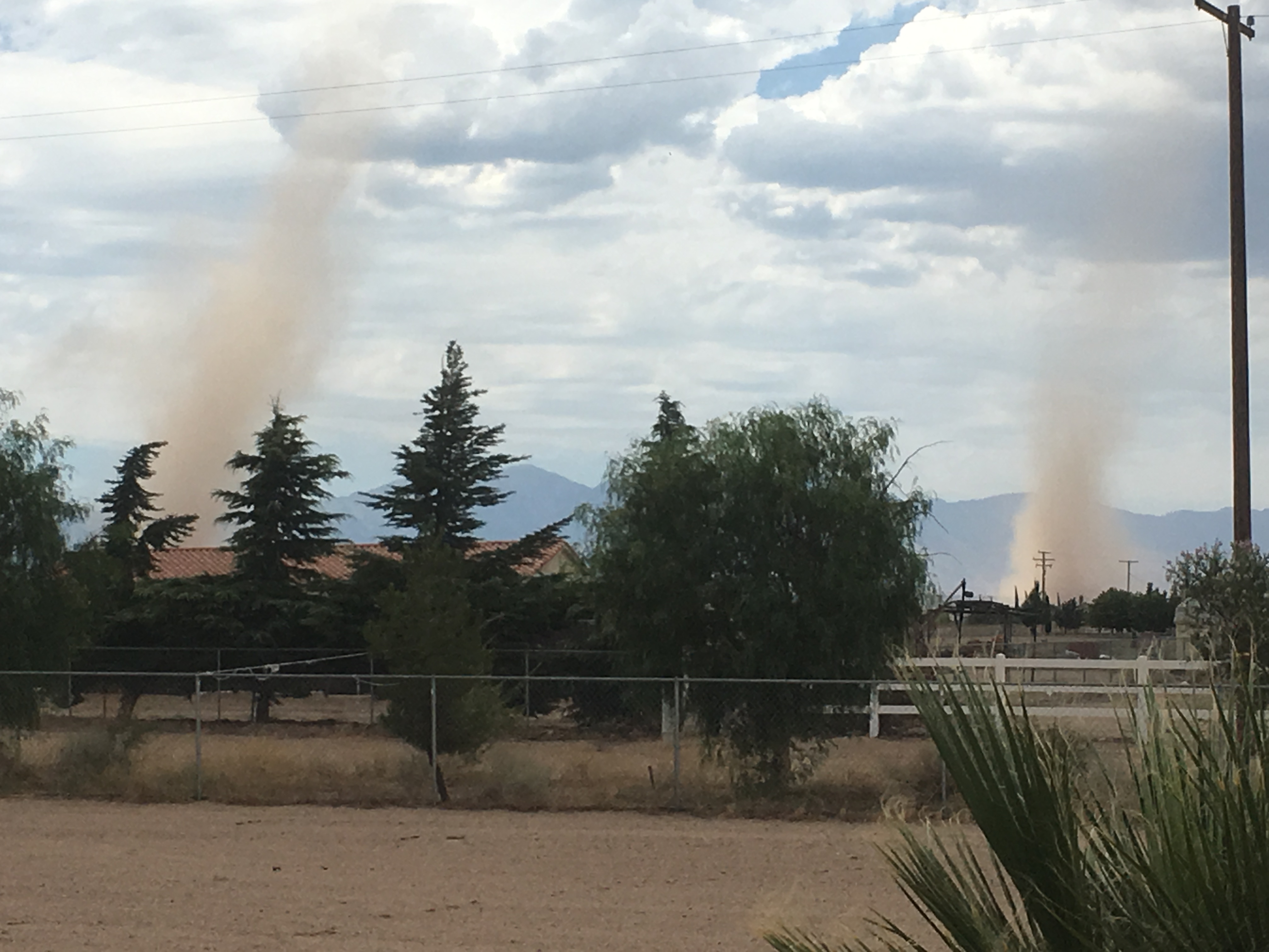
OK there is a picture of a couple of dust-devils here in the dusty desert. They happen everywhere, but because of the dust here, you can see them. It is rotating air. You see the central tube, but it is surrounded by a wide field of rotating air. All the windmills switch directions and lawn furniture goes airborne as they roll through. Wish I could show you the videos, which more clearly show the well-defined rotating tube structure, but they are too many Megabytes to e-mail out of my phone.
Here’s a picture taken the other day of a tree blown over on an otherwise calm day. Raindrops were falling when it happened. Not sure if it was a dust-devil, or a wannabe-tornado, or maybe some combination, but I was standing across the street and heard the CRACK as the tree was slammed to the ground.
How do you think such a stacked-savonius with multiple levels of rope-drives would fare in such a rotating airmass? How about a whole windfarm full of them? Maybe you could get paid to cart away the resulting debris. Maybe they could hold another auction!
I believe that reorientation of the turbines to face the wind requires a frame which also supports the pulleys which direct the power to the cable drive. This frame can be constructed of carbon fiber elements which are light and strong. Adjacent trains of turbines can be connected together by lightweight carbon fiber struts which prevent the turbines from colliding. The philosophy here is to launch a single large turbine system rather than multiple launches.