Savonius AWE kite?

There are some drag devices like Magenn, with some variants about Ideas for scaling up AWES based on a tethered airborne rotor driving a rope drive.

But real Savonius designs are differently shaped, in S with a hole between the blades to increase efficiency, not comprising an inner inflatable cylinder, like on the photo below, from

Do you see a possibility towards AWES with a rope-drive transmission? I think even with a low power coefficient (0.15), this is perhaps a possibility if it can be light enough as it scales, undergoing only the weight of the frame. And stacking unities could be possible in AWES farm in bumper car mode…

1 Like

How to make a Savonius wind rotor using kite technics.

Now put it horizontal in such a way it flies by using Magnus effect, like on the video below.

I experimented a simplified version of the foam device on the last video: for a short time it was flying at an elevation angle of about 40 degrees.

Page 25 (in French language and two diagrams), the S structure of the Savonius rotor is shown:

Among other things, the S-shaped structure is characterized by the space between the two half-cylinders which allows air to circulate and also exert force on the other half-cylinder which returns upwind. This is shown on the diagrams.

A Savonius rotor without this space is not really a Savonius rotor. And perhaps a so high Cp of 0.3 can be explained with this feature when the realization and the proportions are suitable.

The same diagrams on

The figures mentioned on my comment above show the space between the blade.

In the following paper (figure 8), the values of power coefficient (Cp) reaches 0.3 for experimental data.

Energies | Free Full-Text | Experimental and Simulation Investigation of Performance of Scaled Model for a Rotor of a Savonius Wind Turbine

Well Pierre, you are really good at looking up studies and data. The moment I saw this data, I said “wind tunnel”. I note that throughout the publication, they misspell “Tip Speed Ratio”, as “Tip Speer Ratio”. That might be our first clue, as to how accurate ANY of the report is.

Most propeller-type small wind turbines actually are lucky to have a Cp of 0.3.
I think if Savonius turbines could produce a Cp of 0.3 in real life, we’d see a lot more of them.

Also, I read that Savonius tested something like 30 different configurations, and I’m not sure if all of them had the overlap and space in the middle, therefore I am not sure if such a turbine with no space in the middle is not a “Savonius”.

All I can really tell you is something I’ve been saying as long as we’ve been talking about this stuff:
“Professor Crackpot” has predictable behavior, which at the lowest level, consists of placing a Savonius turbine in a wind tunnel and forcing air through it to yield over-optimistic, unrealistic power output data, then publicizes it and people tend to take it seriously.

I’m thinking, realistically, if Savonius turbines could work at this level of efficiency, we would see more of them. I’m not convinced this data is valid. It could even be fraudulent. Hard to say, but if true, I should be out building one right now! When it comes to drag-based turbines, caveat emptor, and proceed at your own risk! :slight_smile:

See also another experimental study. The Fig.10 shows a curve of power coefficients Cp that are very low (about 10 times lower): between 0.01 and 0.03, matching the low coefficients of torque on Fig. 8, but not the data on page 299 that is reproduced below.

Also, page 299:

Savonius investigated the performance of thirty different model of S-rotors in the wind tunnel and open-air [5]. He reported a maximum power coefficient (Cp) of 0,31 from wind tunnel experiments while reported a maximum Cp of 0,37 from open-air tests. In the last half of century, many researchers had experimentally investigated the performances of different designs of Savonius wind turbines and obtained that the number of Cp in the range of 0,15 to 0,35 [6-10].

Very impressive to read. Makes me want to cut a few 55-gallon oil drums in half and build one.
Only thing is, having been in this field as long as I have, and having personally interacted with as many designers and builders of wind turbines over all these years, including a lot of off-grid people, many with home-built systems, all of the significant manufacturers, PhD NREL Wind researchers, etc., I’ve never heard of anyone, ever, actually building a Savonius, or running one. And I will say, nobody takes them the least bit seriously, or to be more blunt, “everyone knows” they totally suck. Or at least that’s what everyone says. That’s what everyone thinks. And that’s like most of the people who know anything in the whole U.S. Either we’re all missing a great design, and nobody in the actual field of wind energy I’ve hung with for all these years knows what they are talking about, or a Savonius turbine for powering the home is something the whole world has somehow been missing for all these decades. Well, I know where to get some oil drums.

One thing to consider is that people who conduct such studies may have a bias toward their favorite pet turbine design, and thereby end up presenting some data that was in error. Another factor could be they only count the half of the turbine that travels downwind as the swept area(?)

Seems interesting how they throw in a Cp/TSR curve from some lift-based turbine at the bottom of page 300, without mentioning it is NOT for a Savonius!!! That, to me, is sneaky at best, and unscientific at worst, and just makes no sense in general. Such a possible deceptive practice might be indicative of their bias to present a Savonius as a turbine to be taken seriously, whereby their research might be taken more seriously. How could an honest researcher throw in data from a different machine than the paper even mentions, without disclosing that fact? Any newbie reading it would assume that is for a Savonius turbine.

You might note, even the way they talk about vertical-axis turbines in this study indicates they don’t quite understand wind energy very well. They say: “The generator of VAWT is placed at the bottom of
central shaft on the ground and the tower do not need to support it.”

This is always the first clue that promoters of the verticals are clueless: They almost always just assume they should all be mounted on the ground, rather than on a tower of any kind, even a low one.

I can tell you just from flying kites, the wind around here can be so low at ground height you can barely get a kite to launch, but up around 20-30 feet high, it wants to pull out of your hand. “There is a reason” wind turbines are usually mounted on towers. That’s where the wind is. But vertical-axis people just can’t be bothered with such details. They are too busy telling everyone how stupid regular turbines are to ever bother learning about the subject matter.

Anyway, if you look into it, there is a lot of fraud, even in scientific research. People want to show good results. Disproving something is good science, but not as sexy as presenting favorable data. So I really don’t know what to say other than “real wind people” “all know” Savonius turbines suck, but at the same time, I cannot think of anyone who has built or run one, at least that I know of at this moment.

You’re good at finding papers on the subject. Maybe you can find one that gives the bad news!

I’ll get back to you if I find anything new to add. :slight_smile:

True, thank you for this observation.

Next to this in a neighboring house, at the top of the gable wall, we can see a Savonius wind turbine, approximately 1 m high and 50 cm in diameter, and which turns in all weather, even in very strong winds. It is been there for years. I see it from home.

My neighbor told me that, according to his owner, the energy recovered was negligible.

OK here is the booklet I ordered from the U.S. Government Printing Office way back in the 1970’s.

Wind Machines - Frank R. Eldridge - Google Books

If I seem to know everything about wind turbines, this is why. I’ve known everything in this book for my whole life. Nearly everything we talk about in these chit-chat groups was already known back in the 1970’s, or actually way before that.

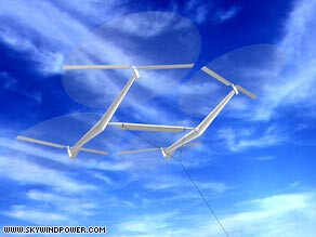
In this book, you can see the progress from vertical-axis machines thousands of years ago, the first horizontal-axis turbines using “Daisy” type rotors with multiple kites in a circular path connected with lots of lines, to windmills with real airfoil blades becoming the main non-animal source of industrial power for Europe for hundreds of years, to early electrical turbine including early Danish designs reminiscent of the KiteX portable camping wind turbine. The booklet predicts the entire subsequent evolution of wind energy, including the nearly ~20 MW machines now beginning to be built and run.

On page 22, the concept of “crosswind” devices is largely dismissed, without even describing what they are, which seems weird. The points to note, for me, are:

  1. “Crosswind” devices (meaning I guess, non-aiming devices with sails mounted on cable loops) had already been dismissed as not efficient, way before Loyd’s Crosswind Kite Power patent in the 1980’s
  2. Apparently, nobody noticed that horizontal-axis turbines are actually 100% crosswind, even more so than “crosswind” devices, since the wind direction is always changing, and horizontal-axis turbines normally maintain aim into the wind!

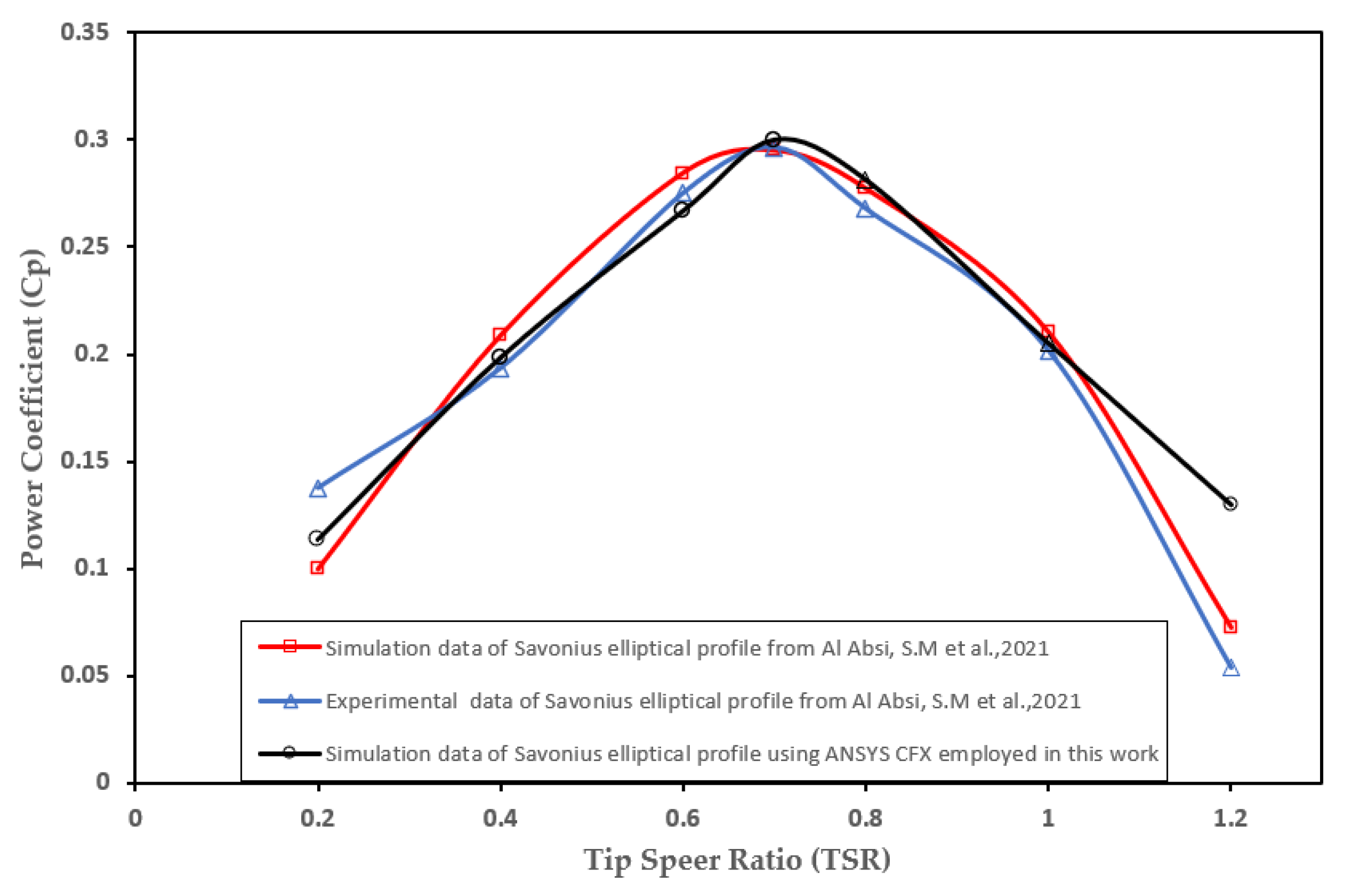
On page 55 is that old, standard diagram of the efficiency of the various types of turbine, at various TSR’s (tip speed ratios). You can see that the Savonius was tagged with a max Cp of over 0.3, while the American Farm Water Pumping Windmill was labeled with a Cp of only about 0.1.

More modern versions of this chart reverse this labeling, giving the Farm windmills the 0.3 Cp, and Savonius the 0.1 Cp number:

Efficiency trends for wind turbines types (í µí¼‚ í µí±¤ ) versus tip… | Download Scientific Diagram (researchgate.net)

Comparison of aerodynamic efficiencies of common types of wind turbines… | Download Scientific Diagram (researchgate.net)

There has always been an emotional debate over when, and why, these number assignments on this now-ancient chart have been swapped, one for the other, and which is accurate(?). Of course, the Savonius devotees always complain that the labeling on the chart was sneakily reversed in order to stamp out the competition for regular wind turbines, while the farm water-pumping people seldom worry about it, because they produce machines that have always worked well for their intended use, and nobody cares much about the details.

Because the farm water-pumper has high rotor solidity and resulting low tip speed ratio, it is considered a drag-based machine, even though it uses blades rotating across the wind. The reason for the low efficiency is the low speed, which gives away half of the possible kinetic energy (proportional to V^2), to wake swirl. So it is said by those familiar with the numbers, that the farm water-pumping rotor has about half the efficiency of a regular low-solidity, high TSR propeller-type rotor.

This would logically place the farm water pumper at a max Cp of around 0.3

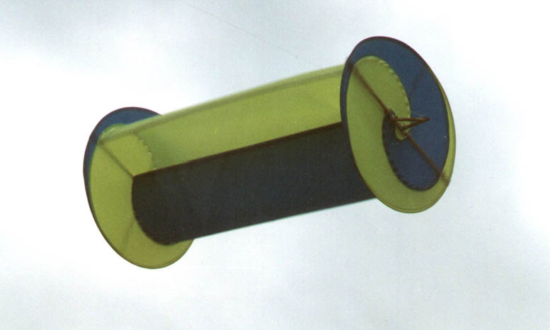
And we all know that with the Savonius buckets traveling downwind, thereby cutting the relative working windspeed in half, minus the energy wasted pushing the buckets upwind, combined with the fact that only half of the machine is predominantly producing, rather than using energy, even while doubling the officially-recognized swept area, it would be difficult for a Savonius to operate “efficiently”, according to offical requirements for such measurements.

That would logically suggest the Savonius might enjoy a Max Cp of around 0.1

So my opinion is the labeling was accidentally reversed on the old chart from the 1970’s, and was subsequently corrected. But the question remains, why is this old chart seen as even 100% factual, with the only question being of which label to attach to which curve, when so many decades of measurements have been produced since then? Weird, huh? Well, that is a window on human nature. Once something is stuck in our heads, it is nearly impossible to replace. Think of official “religion”…

Maybe BOTH curves are a little off. Maybe they both have about the same curve! But I’m gonna go with a Cp of 0.3 for farm water-pumpers and a Cp of 0.1 for Savonius, because that seems to be what everyone who knows anything (“real wind people”) agrees with. The main “advantage” to Savonius turbines is they appeal to people with zero knowledge of aerodynamics and “lift” because “any idiot” can intuitively understand how they work. Period. So, who likes them, and for what reason? Idiots, because they are idiots! Not that complicated! (assuming, of course “real wind people” know what they are talking about…)

The funny thing is, after all these years, people are STILL photocopying and quoting this now-ancient chart. In all these years, nobody has made a new chart that differs from this.

OK now, I’ve gotta go get some oil drums. Because Pierre has discovered that Savonius turbines have a Cp of 0.3, and I need to start building them!!! :slight_smile:

In this paper, see the “Figure 5 – Streamlines around turbine with no gap (left) and with a gap (right)”, and the corresponding text pages 4 and 5 (just below the Figure 5):

Blackwell et. Al. from Sandia laboratories [6] were testing 15 two and three buckets configurations. They were changing the non dimensional gap size and the orientation for the three buckets configuration. Yet they used only circular sections.They found that except starting the two buckets configurations showed better performance, 0.24-0.28 power coefficient at 1 unit speed ratio (tangential velocity over wind speed).The three buckets configurations reached to only 0.14-0.16 power coefficient for the same speed ratio. The latter configuration performed as reported in fig. 3 but the two buckets with an opening is almost double in efficiency.

The Fig. 3 represents the old standard diagram where Savonius is tagged with a max Cp of about 0.15.
With the gap (Fig. 5, right), and above all with the two bucket configuration which is far more efficient than the three bucket configuration (see also the following comment), in the last sentence it is said that the efficiency (Cp) is almost doubled.

Numerous studies mention Cp of about 0.25-0.3. The gap probably changes and improves aerodynamics of streamlines around the turbine as also mentioned on other papers, but not so much (see the Figure 39 related on the following comment).

The correct reference is [5] and is linked below the reference quote:

  1. Blackwell B. F., Sheldahl R.E. and Feltz L.V. Wind Tunnel Performance data for two and three bucket Savonius Rotors, SAND76-0131, Sandia National Laboratories.

The difference of efficiency between two and three buckets seems to be much larger than the difference from gap (opening) and no gap.

Indeed the Figure 39 (a) page 84 represents max Cp of 0.22 with no gap (s/d = 0), a little less with gap (s/d = 0.2), and 0.24 with gap (s/d = 0.1 to 0.15).

Thank You Pierre, for some more interesting information about Savonius.

  1. Regarding the increased performance with a gap between the buckets: I’ve always assumed the air blown backward into the upwind bucket helps prevent a vacuum behind the upwind bucket, decreasing its upwind drag. I guess in an extreme case, there could be enough air transfer to actually propel the upwind bucket upwind by pressure behind the bucket, but I doubt there could be enough air to achieve that level of drag reduction/actual propulsion.

  2. Did they adjust the “swept area” when changing the gap between buckets as that changed the diameter?

  3. The fact that they used a wind tunnel is nice for them, as “scientists”, wanting to have a lot of control over their apparatus and conditions, however, there is a standard procedure for measuring small wind turbine performance, and that is in open wind, using a nearby anemometer at the same height, running a generator, with electrical power output measured, and a standard power curve taken. The configuration in this test was nice for comparing the various configurations, but would not be accepted for certification of an actual model. Taking data at times when everything seems to have achieved an equilibrium may not reflect real-world operation. The turbulence and direction changes of the wind these turbines are said to be optimal for, are not duplicated in a wind tunnel. They appear to have somehow addressed the wind blockage, and forced-air issues with wind tunnels, but have they really? Can wind tunnel testing really reflect a Cp seen in real-life operation?

  4. I saw an inordinate amount of attention going toward measuring bearing drag, and its effects on torque measurements, etc., however, let’s remember that any real turbine will always have bearing drag anyway, so why pretend otherwise(?), and meanwhile, as “real wind people” know, once a turbine is spinning, bearing drag is not a significant factor.

  5. Using some air pump/compressor as a “load” seems very weird to me. This is the first time I’ve ever heard of anyone taking wind turbine data using an air compressor as a load, or using a load that was able to spin a turbine faster than the wind. Was the power data taken from an air compressor valid data?

  6. I can see how the two-bucket version would be most efficient - less air friction and air resistance in total, and less wind blockage from one bucket to the next. And at that point, obviously, a two-level machine with the levels offset by 90 degrees would yield better startup behavior.

The Savonius research from Cal State Long Beach I’ve mentioned may have been from Hamid Rahai. Here is a patent with his name on it, for an improved blade profile for a Savonius:

US7393177B2 - Vertical axis wind turbine with optimized blade profile - Google Patents

This sounds like the same research I saw from Cal State Long Beach several years ago.
Interesting how researchers such as the Sandia folks so often cite using “oil drums” to build these machines. Without that ready-made source of “blades” (buckets), the design might not get as much attention, since as you can see by the projects that try to create their own buckets, that alone is enough to stop their efforts for years on end, since processes like machining, bending sheet metal, and welding are beyond their normal experience and skills.

So that Cal State Long Beach research by Hamid Rahai may be something you can find, as a further source of information.

I will mention something else that occurred to me about Savonius turbines showing a “tip speed” faster than the wind speed: it may be that the inner parts of the rotor are doing most of the work, pushing the outer parts of the buckets faster than the wind due to the larger circumference at the higher radius being pushed faster by the inner parts of the buckets. This might imply only the inner part of the rotor is doing the pushing.

Anyway, what I would like to see is a power curve taken in actual ambient winds using a turbine with a generator and an anemometer. Somehow such actual, real-world measurements seem beyond the interest or capabilities of Savonius advocates and researchers.

No. Page 3: “Rotor Diameter (nominal) 1 m”; “Bucket Overlap 0.0-0.1 m.” Page 14: “The diameter of each bucket is 0.5 m.”

Hi Doug, thank you for your observations.

I would add that in the context of AWE, the Savonius rotor is a (if not the only one) thing achieving both steady-state continuous power generation and lift, being stationary, without requiring a lifting kite.

Even with a low Cp, certain versions could be studied (apart Magenn which is not really a Savonius rotor because of the central large inflated balloon which leads to big loss of efficiency).

Hi Pierre: I’m not so sure a Savonius rotor is the only thing that provides both power and lift at the same time.
Don’t forget about SkyWindPower from Shepard www.skywindpower.com
image

And of course you have Makani and all the flygen variants (although not stationary), not to mention SuperTurbine™, which, like the SkyWindPower flying machine with its tilted rotors, does provide both lift and power at the same time, even when stationary.

I would say a self-elevating, flying Savonius wind generator of some type would be worth the trouble for someone to at least try though. We never know when something might turn out to be useful or instructive, or maybe leads to a more productive variant. :slight_smile:

1 Like

Thanks for reminding me.

Can anyone find an example of an oil drum turbine operating? How about some power data on meters? I’ve done some looking, and all I can find are projects by first-timers that make zero power, usually not even connected to a generator. Some of them fall apart during the videos. Most are just shown spinning, making no power, as though that proves anything. Many use plastic barrels. Seems like such a popular design, promoted for at least 50 years, might have a few successful examples.
I’m still trying to find one.

Here’s the “best” one I’ve found so far:

Prototype VERTICAL AXIS, Oil Drum VAWT wind turbine 24V FREE ENERGY PROJECT. (youtube.com)

Pretty pitiful.

This Australian site shows an oil drum turbine being built and set up.

Vertical Axis Wind Turbines. (micropowergrids.com.au)

it doesn’t show one running, nor give any data. But it does say this typical incorrect info:
Vertical Axis Wind Turbines (VAWT):

PLEASE NOTE: We ONLY offer Vertical Axis Wind Turbines, as VAWT’s are 30% more efficient than HAWT wind turbines.

VAWT’s are Superior Wind Turbine technology as the Bearings & Rotation are ONLY on One Axis, as well as VAWT’s are omni-directional, meaning they will generate Power with the Wind blowing from Any direction!

VAWT’s output Voltage range from 12V ~ 480V Three-phase AC, the Turbines use permanent magnet disc core, direct drive generator, VAWT have a better visual appeal with low operating noise.

Horizontal Axis Wind Turbines (HAWT):

We do NOT offer Horizontal Wind Turbine due to there inherent problems of two different Axis of Rotation causing premature failure of the Bearings, e.g. The Horizontal Rotation of the Blades are constantly Fighting against the Vertical Axis Rotation of the Mast Bearing, those multi directional forces is what causes nearly every HAWT Bearings premature failure.

***** So basically, they are admitting they can’t even build any sort of turbine that works, while claiming that vertical-axis turbines are “superior” and “30% more efficient”. It never ends. Show the world an oil drum turbine properly operating, with data.

This guy says in the comments to this video that his oil drum windfarm only makes power over 20 mph, but has to be shut down over 30 mph. Says it normally only functions as a wind sculpture but has occasionally woken up to fully charged batteries after strong winds.

55 gal Drum Savonius Wind Turbine (youtube.com)