Magenn

The ratio of Magnus power consumption to the generated power is a significant concern.
The paper I already mentioned and I put again gives some data allowing to begin to know it.

https://www.sciencedirect.com/science/article/pii/S0167610518307396

Some data come from the paper.

Magnus power consumption:
Cylinder 3.73m x 1 m, projected area = 3.73 m², area = 3.73 x π = 11.7 m².
530 rpm (figure 13) lead to 27.7 m/s = tangential speed
Air density = 1.2

The equation 3, which is on the last page 29, 3.4. leads to a numerical example from data on the paper:
0.007 x 1.2 x 27.7 x 27.7 x 27.7/2 x 11.7 = 1044 W (the curve on the figure 13 is on about 1000 W, matching the value given by said equation 3).

(Another formula (for AWE, chapter 12, page 293, AWEbook2018) would give a far lower ratio by wind speed cubed x spin ratio X not cubed.)

The potential power for said cylinder would be, in not crosswind yoyo mode (like Onmidea’s balloon):
Power in reel-out phase:
Wind speed = 13.85 m/s (the same wind speed as previously)
Speed reel-out: wind speed/3 = 4.61 m/s
Spin ratio k = 2 leading to Cl = 4 (by the figure 4). Spin ratio k x wind speed = tangential speed (here 27.7 m/s)

½ 4.61 x 1.2 x 4 x 13.85² x 3.73 = 7916 W, and 5141 W after loss by cosine cubed at an angle of elevation of 30°, or 2798 W after loss by cosine cubed at an angle of elevation of 45°.

So the data (figure 4 about lift coefficient, figure 13 about power consumption, equation 3) on this paper could confirm at least partially the values given by Omnidea’s experiments on https://collegerama.tudelft.nl/Mediasite/Play/e51a679525fe491990de3a55a912f79d1d,
the power consumption/ generated power being about 1/4 during generation phase, and being about measured 500 W (and also about calculated 250 W) for a balloon of 40 m² projected area, and for a tangential speed of about 6.55 m/s (from 50 rpm on the presentation), while the figure 13 indicates about 125 W for 13.85 m/s (from 265 rpm), the cylinder being 3.73 m² projected area.

The lift of said cylinder would be ½ x 1.2 x 4 x 13.85² x 3.73 = 1717 N.

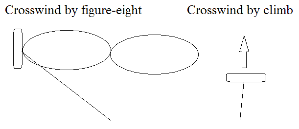
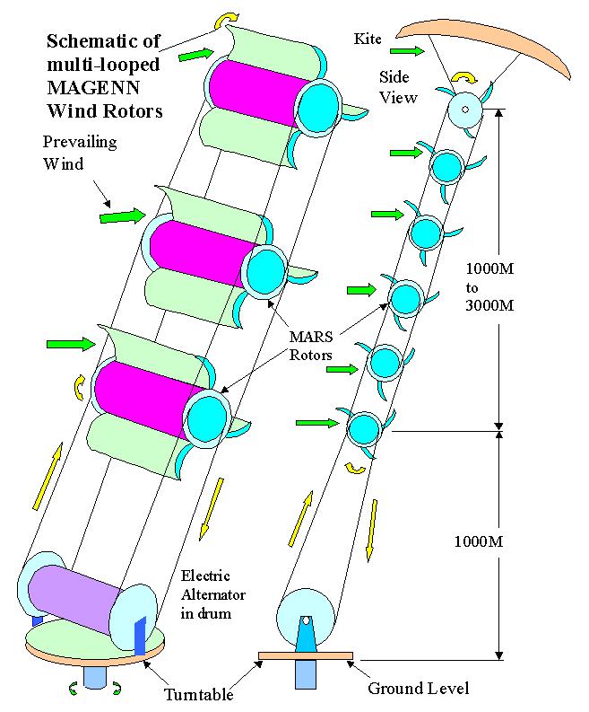
I wrote some parts of this message before but now it becomes clearer for me. More I look after Magnus wings, more I see them as one of promising solutions for AWES, in spite of the high power consumption value at a high (but not always essential) spin ratio value. The main advantage is the potential of maximizing space, but not necessarily using known methods such as yoyo (Omnidea) or flygen (Magenn), or even figure-eight crosswind yoyo as described on the paper on Magenn.

1 Like

Ok. So this will be a long post. I did some calculations.

So the thing I will be discussing here is a magnus based AWE rig working in Lift mode (Yoyo), but with a energy harvesting device onboard (drag mode turbine). The drag mode turbine will harvest energy that is used to rotate the magnus wings. This is not necessarily a sensible design, just a basis for the calculations. The design has one tether and one wing, but you could make variations with more wings and such, the math is more or less the same anyway.

w - wind speed
G_e - glide number for magnus wing at speed ratio k
G_{e,\Sigma} - glide number of magnus wing and power harvester together
\eta - efficiency of power harvesting, ie losses from creating drag to making magnus wings rotate
C_L - lift coefficient of magnus wing
C_D - drag coefficient of magnus wing
C_{D,\Sigma} - drag coefficient of magnus wing and power harvesting device
l - length of magnus wing
c - chord/diameter of magnus wing
k - speed ratio apparent wind vs speed of magnus wing skin
C_f - friction constant from paper, value 0.007 Experiments on a Flettner rotor at critical and supercritical Reynolds numbers [1]
P - power generated by the rig
P_m - power consumed by motors to rotate magnus wings
D_m - drag force of magnus wing harvesting device
D_\Sigma - Drag force of wing and harvesting device together
n - loss factor to account for cosine loss, roll loss etc, 0 < n < 1
w_a - apparent wind at the kite

We’ll start looking at the apparent wind speed of the kite. I wont get into details, but lets assume it is:

w_a = n G_{e,\Sigma} w

That is, the kite is moving with the wind speed times glide ratio, deducted cosine losses.

The power necessary for the magnus rotation motors are

P_m = \frac{1}{2} C_f \rho (k n G_{e,\Sigma} w)^3 \left( \pi l c \right)

Using power equals to speed times force we get

D_m = \frac{P_m}{w_a}

D_m = \frac{1}{2} C_f k^3 \rho (n G_{e,\Sigma} w)^2 \left( \pi l c \right)

Next, we calculate the total drag of the wing and harvesting device

D_\Sigma = \frac{1}{2} \rho (n G_{e,\Sigma} w)^2 C_D l c + \frac{1}{2} \frac{1}{\eta} C_f \rho k^3 (n G_{e,\Sigma} w)^2 \left( \pi l c \right)

D_\Sigma = \frac{1}{2} \rho (n G_{e,\Sigma} w)^2 \left( C_D + \frac{1}{\eta} C_f k^3 \pi \right) l c

We can see from this equation that the effective drag coefficient is

C_{D,\Sigma} = C_D \left( 1 + \frac{C_f k^3 \pi}{\eta C_D} \right)

G_{e,\Sigma} = \frac{C_L}{C_D \left( 1 + \frac{C_f k^3 \pi}{\eta C_D} \right)}

G_{e,\Sigma} = G_e \frac{1}{ 1 + \frac{C_f k^3 \pi}{\eta C_D} }

Next, we’ll assume that the kite is being reeled out at one third wind speed (proven optimal in theory). Thus the power generated by the rig is

P = \left(\frac{1}{3} w \right) \left(\frac{1}{2} \rho n^2 G_{e,\Sigma}^2 w^2 C_L l c\right)

P = \frac{1}{6} \rho n^2 G_{e,\Sigma}^2 w^3 C_L l c

P = \frac{1}{6} \rho n^2 w^3 C_L G_e^2 l c \frac{1}{\left( 1 + \frac{C_f k^3 \pi}{\eta C_D} \right)^2}

Now to analyze this, we see that the power is equal to the nominal power of the wing without the power harvesting device, multiplied by a harvesting/rotation loss. The [square root of the] denominator of this factor is:

1 + \frac{C_f k^3 \pi}{\eta C_D}

Let’s select some test values. We assume \eta = 0.5, 50% loss in powering the magnus motors. Lift and drag coefficients for different k were «lifted» from the paper [1]. Some values of k give us:

      ____ (50% conv loss) ____      ____ (0% conv loss) ____
 k    losses [%]    C_L^3/C_D^2      losses [%]    C_L^3/C_D^2        
 1.0   7.54152      4.28501            3.88161     4.54195
 2.0  31.3559       9.18151           17.877      12.0145
 3.0  56.5068       8.53804           36.8272     14.9459
 4.0  74.2496       5.79932           54.6728     13.5438
 5.0  84.8691       3.50258           68.6289     10.4565
soft kite (*)       6.3       

*) Reference soft kite with C_L = 1.0, G_e = 2.5

Optimal value of k seems to be around 2.3 for conversion loss 50% and 3.1 without conversion loss.

For this rig because the C_L is huge and G_e is kind of average, the rig produces more power compared to a soft kite for a given projected area. Since the G_e is already quite low, tether drag is relatively less important so it can use relatively longer tethers before stalling.

The second column is the loss due to spinning the magnus wings, while the third column should be proportional to the power generated. The loss is relevant for Betz limit considerations and also the dimensions of the magnus motors.

Then to the bad point: I did some quick simulations (100% unverified, so they may be wrong) but the rig did not respond well to mass. This is because the glide number is poor I guess. So in particular for this rig, where we need both rotating motors and harvesting turbines onboard its going to be a challenge to get this thing working in light winds.

I gather the magnus based turbine is intriguing but not the most promising direction for AWE overall…

3 Likes

Bravo for all these calculations. It looks to be a crosswind Magnus AWES like on the paper I uploaded on Magenn but with some improvements such as the energy harvesting device onboard for the inventive aspect, and more parameters for the scientific aspect.

I upload again the paper studying crosswind flight by figure-eight, then another paper from the same author studying vertical trajectory (something like Omnidea but with a higher spin ratio). Both are optimized, and with a wind speed of 10 m/s. I put also a third file to summarize the previous files.
Magnus effect airborne Hably page 7 power formula.pdf (1.7 MB)
Control of an airborne wind energy system.pdf (2.0 MB)
Crosswind%20Magnus
The first paper states a power of 1.47 MW for a cylinder of 500 m² (with crosswind figure-eight). The second paper states a power of 1.48 kW/m², so two times less. The second paper states also there is a crosswind component (with vertical trajectory) when the lift to drag ratio is high enough.
The advantage of figure-eight is that all the figure is in the powerful part of the flight window, while the vertical trajectory goes quickly too high for an efficient harvesting power. In the other hand for a Magnus wing the vertical trajectory can be easier to control.

In all cases there is a huge advantage of Magnus wing thanks to a slow flight, inducing both less risk and less tether drag (with an option to higher reachable altitude), and above all maximizing more the space used.

Disadvantages can provide from the gyroscopic effect in the maneuvers such as transition phases.

Reading the first paper, it mentions some C_L and C_D numbers from Reid (1924) using a high AR magnus cylinder and getting some very good numbers. Their max \frac{C_L^3}{C_D^2} number is 69.44 which is heaps better than mine at 14. I think this probably relates to my adding the energy harvesting device on the wing. It would be interesting to redo the calculations with the numbers from the Reid paper though.

More on the same path, I was looking at minimum flying speeds today, and the magnus rig has a lot of things working against it. If it can be lightweight, then good, but if it turns out heavy (as I expect) then low wind ability will suffer.

It seems kites with low glide numbers like this (slow kites that you also seem to like for other reasons) are poor at light wind performance. Poor glide numbers such as those we are looking at here probably translates to the equivalent of 20-30% added mass, compared to a medium drag rig, and more than 100% added mass compared to a high efficiency wing. This in addition to the fact that you need the energy harvesting device, support and motors for the magnus wings, all adding weight.

On the more positive note, the \frac{m}{C_L S} ratio may still be low due to huge C_L, being the defining ratio for minimum windspeed for AWE rigs.

In 4.3 from this paper “Note that embedded motor consumption to rotate the Magnus cylinder has to be subtracted from this value in order to have the total net power produced.”
And the motor consumption increases with the cube of the Magnus wing tangential speed. For a crosswind use this consumption can be still relatively higher due to the apparent wind, multiplying glide number by the cube while it is only squared in the power formula, under the form (Cl/Cd)², if I am not wrong.

From the calculations on Magenn and all things being equal, Omnidea’s balloon power consumption is almost 4 times that of the cylinder of 3.73 m x 1 m from the paper, this with all the reserves due to approximations. From some experiments I am doing I saw that an inflatable cylinder rotates with difficulty if it is not well inflated. As an hypothesis the inflatable balloon could be slowed down because of the windward grip digging the balloon. If this point is verified spin ratios of 2 or 3 are unlikely with an inflatable balloon unless high internal pressure can be reached. However even a low spin ratio of 0.5 or 1 can be interesting for other reasons.

1 Like

An interesting concept is shown as the “Schematic of multi-looped Magenn Wind Rotors” on
http://www.energykitesystems.net/0/Magenn/, attachment below:


“1. How might the generator be groundstationed? Magnus-effect autorotating tethered non-powered aircraft (kite wings) on a loop scheme with generator on the ground? Not laddermill, just loop being driven by the rotation of the lifting wings. Notice the wings stay aloft and that the winged sector can be in and stay in very high altitude. Severe lifter kite or kytoon could assure tension and staying capacity. Drawing by Harry Valentine. [ED: Magenn Power, what do you think about leaving the generator on the ground?]”

1 Like

My investigations shows the Savonius windmill to have an optimal TSR (tip to wind speed ratio) a bit less than 1.0. Magnus though should have a speed ratio r corresponding to TSR > 0.5. So I dont believe it is a valid solution to have a small radius magnus wing at the senter of a Savonius turbine, like the picture shows. If it should happen, I guess parts of the axial length for savonius and parts for the magnus wing would be the way to go, adapting the radius of each section for optimum operation.

The Darreius turbine though har TSR of 4 and could possibly house a useful magnus wing at it’s core.

Anyway, these are solutions that are simple because there are no gears involved. I think the interesting number for harvesting energy on a kite is the efficiency of harvesting, which must mean the amount of drag created. I would think an efficient wing is a requirement to mininize this. Probably leading us to a «windmill» type turbine, or possibly even something looking like rotary AWE mounted on the wing (for maximum power to weight, and minimum drag).

In the past I flew a poly (full, with no cylinder inside) Savonius rotor of 0.27 m diameter and 0.54 m span, alone as a kite, then with a poly cylinder of same dimensions of the side: both flew, and with an elevation angle of about 40°. Both had end disks of 0.32 m diameter. The cylinder seemed to have a little more lift than the Savonius rotor.

I experimented also a Darrieus rotor of 0.5 x 0.5 m with said Savonius rotor on a side, and with said cylinder on the other side: this was too heavy to fly but the rotation was almost as fast as the Darrieus rotor alone, and the Magnus effect was perceptible.

The diameter of the Savonius rotor on the picture (and also for Magenn) should be considered rather than the diameter of the cylinder inside (imho), because the rotation of a Savonius rotor generates a Magnus effect which is used to fly a Savonius rotating kite. In the other hand the cylinder inside withdraws some powerful area from the Savonius rotor.

But @tallakt’s remark could apply for the large Savonius rotor driving a small Flettner rotor on
A review of the Magnus effect in aeronautics.pdf (4.4 MB) on the figure 5.

1 Like

If left and right are independent on the drawing, the kites could be made to fly crosswind figure of eight by controlling the torque on either side

I’d like to see it get hit by a big dust-devil. Which it quickly would in most Southern California windfarm-class locations. Or any severe turbulence.
Watch this video:


Hypothetical solutions may look attractive, but Mother Nature does not always care about how neat a diagram looks.
1 Like

We dont have these in Norway…

1 Like

…although…

2 Likes

Today I done some experiments with an old solar balloon of 3.1 kg, 2.7 m diameter and 10 m span, then 7 m, then 4 m as it deflated. In the end a swivel which was not too useful. I rotated the balloon on a half rotation, sometimes a whole rotation. With my arms I obtained a maximal tangential speed of about 4 m/s with 7 m span, and as expected more with 4 m span, less with 10 m span. So the power consumption is a real concern, above all with inflatable balloons with low internal pressure that are subject to deformation due to air friction and also real wind.

1 Like

Yeah cuz Norway suffers from a dust shortage.

1 Like

I hope no offence was taken, just trying to be funny. You’d have to take local weather into account of course. We have weather issues in Norway as well. I’d say saltwater and iceformation or extreme cold could be some issues we are facing here. Im sure most rigs would fail miserably in a dust devil unless some precautions were made

Yeah, me trying to be funny too. Dust devils are just one artifact of “thermic turbulence”, caused by the sun heating the ground, which heats the air. I think they can happen anywhere the sun is over a certain angle in the sky. I get hit by one every few months. Forst you notice it getting suddenly windy, then you see trash and lawn furniture flying, then the dust swirling and the vacuum-cleaner sound. Loud when they hit a Joshua tree with all those spines. I had one come at me while getting ready to launch a hang-glider. I was strapped in and had the urge to fly through it (bad idea). I instead walked forward through the control bar and grabbed the nose and pointed it down. It came up the hill but missed me by maybe 40 feet. Other people are not so lucky and we have memorial benches and plaques for them with their names engraved. I’m guessing there is the occasional dust devil even in Norway when the sun is high, like say June 21. But without a lot of dust you might not notice it. Similar phenomenon to waterspouts. Here in Southern California, every wind turbine, large or small, must handle dust devils and thermic turbulence in general, storms, 70 MPH winds or worse, etc. Really, every region has its own version of whacky weather and unexpected turbulence, including severe storms. Beginners always say they will just watch the forecast and take their stuff down when severe weather threatens, but in many locations, that means shutting down your system when it would be most productive. Plus, it’s hard to have someone on site at all times. People need a vacation or time off once in a while. Bottom line is every wind energy systems needs a means of overspeed protection, or, as I like to say, overspeed protection is not the main thing, it’s the ONLY thing. For short-term testing you can usually get away with a system that has no overspeed protection, since you are there watching and can pick your medium-wind-speed day, but for installed systems, experience says it’s the most important thing of all.

1 Like

I think every system which operates at a high efficiency, ie high glide number for the blades, has an advantage in «nuclear» wind gusts as they are nominally operating at very high speed relative to the wind. With an efficient wing, you can quite easily add a bit of drag or reduce the lift slightly, and the depower effect is huge.

This is one of my major concerns with the magnus effect based rig. The cylinder is large and operates at low efficiency. So the depower available to the system is very limited.

Lets say you could reduce the lift+drag by a factor of 3 for a magnus rig (with C_L between 0 and 4 and C_D at 1.0). You are producing max power when a gust hits. The gust is 3x nominal wind speed (going from w to 3 w).

Lets say nominal speed (accounting for 50% cosine losses) is 2x wind speed, and force is approx:

L = \frac{1}{2} \rho 2^2 w^2 C_L S

After the gust hits, you apply full depower and get only the drag force on the tether

D = \frac{1}{2} \rho 3^2 w^2 C_D S

We can see that for these numbers D is still only 56% of the tether tension you had in production. So the magnus rig might even survive this gust.

Sure, you lost flying ability and flying the cylinder with only drag is going to be a bumpy ride, but you survive.

I think the important distinction is whether or not you are flying crosswind, and how high the glide number is.

Going back to the starting point, Magenn and Omnidea did not have crosswind flight, and that is why I did not see them initially as fully utilizing the concept of the magnus wing. (The addition of lighter than air gas making them even less viable in real life use)

1 Like

An interesting remark that deserves to be detailed. On theControl of an airborne wind energy system.pdf (2.0 MB) I attach again, page 6: “For a vertical trajectory, the spin ratio will take a value between X = 5:4, which maximizes power without taking part of the relative wind, and X = 3:6, which maximizes the crosswind power if one reaches the relative speed vr = L/DV.”

This seems indicate that Omnidea’s vertical trajectory generates also some crosswind power, that without fully use it by flying in figure-eight or loop. It is also perhaps a reason why the efficiency is expected to be about 2 times less, and not yet less, that the efficiency of a Magnus effect-based AWES in crosswind maneuvers (1.7 MB).

That said using crosswind flight would allow maximize the very high Cl and overcome the huge power consumption for a high spin ratio. I am not sure it is really possible with inflatable cylinders unless the internal pressure is high enough to prevent significant deformation.

1 Like

I am calling Omnidea «not crosswind» because though the vertical motion is crosswind, the kite has limited L/D and thus will fly a bit into the wind. So when you reel out, you do get crosswind motion, but you also get downwind motion. The downwind motion will severely limit and counteract the effect of crosswind motion.

My definition for crosswind AWE after saying this would be something like «going crosswind with a fixed tether length».

You also want the speedup of the crosswind motion to enable low weight harvesting of energy onboard for spinning the magnus wing.

1 Like