You could do the equation yourself. My assumption has been that only the air closest to the envelope gets perturbed by the envelope. If the envelope was a smooth cylinder this boundary layer might only be a few centimeters. The more uneven the cylinder, the faster it is spinning, the more viscous the fluid, the greater the height of this boundary layer I think. Perhaps the equation in the paper is the correct one to calculate it, or has some of the right variables.
I don’t know if the paper is applicable though as there the particles are forced to move, while in your case they only move if they are within the boundary layer
A separate question is how this boundary layer interacts with the natural convection inside the balloon, and how that depends on the strength/size of either.
What would happen if there were no convection and the fluid was very viscous and the cylinder was very small and was spinning very fast, and what would happen in the opposite case?
But say you attach baffles to the inside of the envelope that rotate with it. Or say you are only interested in the air within the boundary layer, now you can calculate the ratios of the centrifugal and buoyancy forces, if you make some assumptions about rotation speeds and temperature differences.
Now if you know the ratios of the forces you can decide if adding the baffles helps or not, or where you should put them.
A publication which is also available on Researchgate provides interesting figures 3 and 4:
Margarita Khusnutdinova, Aigul Haibullina, Alex Sinyavin and Aidar Hayrullin
Kazan State Power Engineering University, 51 Krasnoselskaya Street, Kazan, 420066, Russia
Many parameters remain to be known to know if a Magnus effect-based balloon could improve the insulation of contained heated air: the volume, the diameter, the angular speed, the temperature gradient, the degree of interference between the layers according to these parameters …
However, I would make a remark: we can predict that the effect would be limited during pumping mode cycles due to the variation in the rotation speed going as far as its stopping or even its reversal. It is the reason why I rather see an use in static mode (which is mentioned in the preprint), i.e. for Is an electrically heated balloon lift support for AWES possible? And for gigantic balloons the time to achieve stability of the maximal heat could be very long, perhaps several hours or even days. But there are only hypotheses.
A heating wire (like below) with adapted electrical resistance and battery could be settled in the middle of a balloon. Then measuring the aerostatic force when rotating (and the time to achieve maximal heat) and when not rotating and comparing.
Thermography of a filled and ready to go hot air balloon.
Now I would wish to see the image of the same balloon when rotating.
Hot air balloons sometimes use rotation vents (see below). Would the (low) rotation speed be sufficient to see if the colder layers are against the walls inside, and after how long, and at what speed of rotation?
ROTATION VENTS
Rotation vents enable the balloon to be turned so that it is correctly orientated for landing. When flying a partitioned basket or one with a door , rotation vents are mandatory.
That said, the measurements would be distorted because of temperature exchanges due to the vents.
The temperature in a hot air balloon is far higher (about 70 to 100 degrees more in relation to the outside temperature) than that of the intended Magnus effect-based balloon (2 to 10 degrees according to the dimensions of the balloon). This must be taken into consideration. Perhaps also the horizontal axis of rotation of a Magnus effect-based balloon leads to some differences.
As I mentioned above the static mode would be required to keep the benefit of insulation by the rotation, above all if along time is necessary to achieve it. Flettner balloon and VAWT side by side leads to a static (stationary) operation. If the results are better known, some designs of hot air with central heating cables could be introduced in the designs mentioned in the preprint Vertical axis wind turbine(s) connected to Flettner or Sharp balloons, avoiding helium or hydrogen and their respective issues.
An advantage compared to other yo-yo AWES including parasails: the alternating phases of reel-in and reel-out do not change the structural configuration through folding or other depowering techniques, but only the velocity (and perhaps the direction) of the rotation. That could mitigate the wear due to the terrible yo-yo mode. This is likely a small advantage, nothing more.
As an external layer to protect the inner hydrogen-inflated balloon (see below).
To complete the initial preprint.
The video (again), just on a sketch:
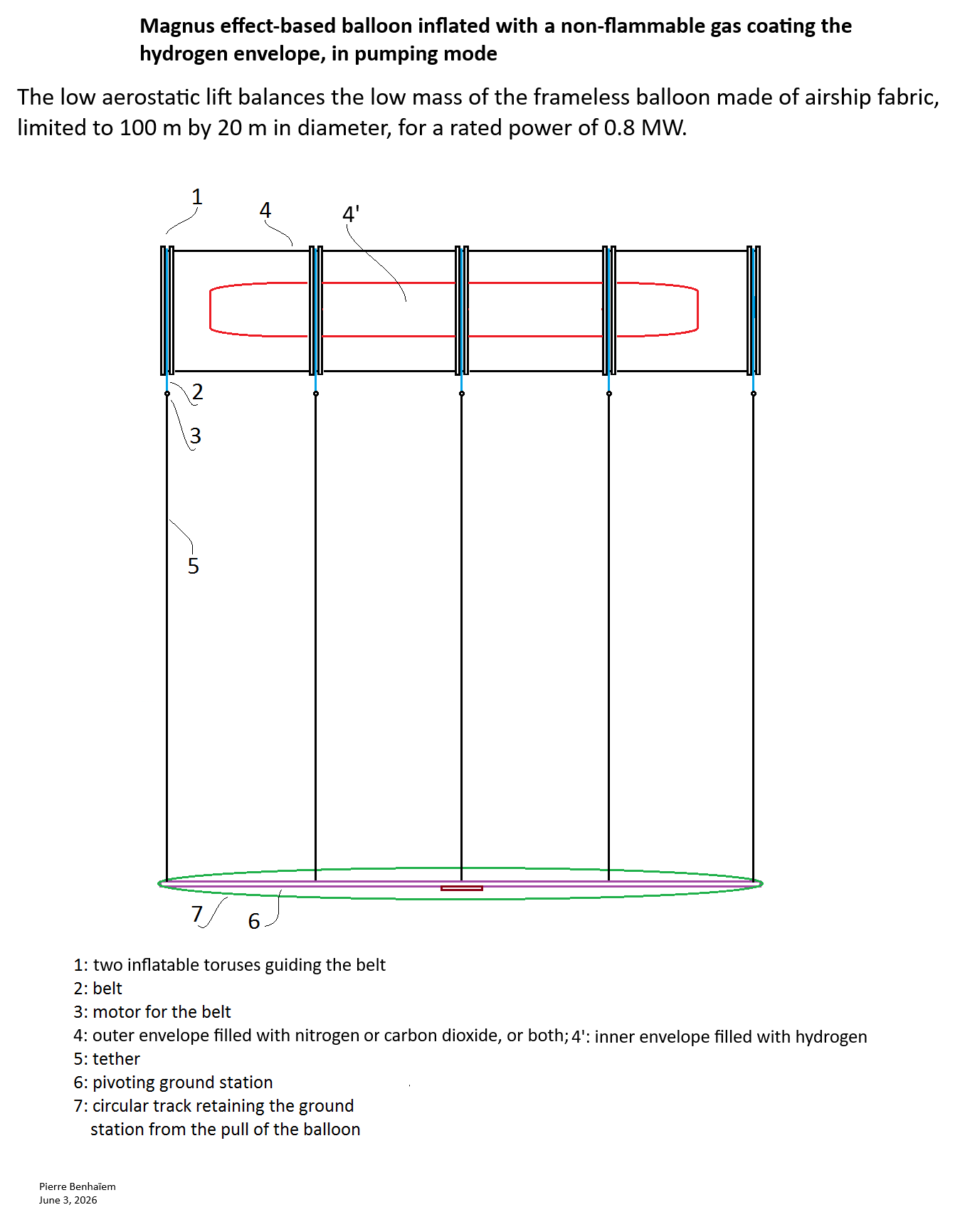
As the Magnus effect-based balloon is rotating, only nitrogen would be used to protect the internal hydrogen-inflated envelope.
Since, in pumping mode but not as a lifter, high aerostatic thrust is not required, and must be almost neutral, two less expensive inflation configurations are presented, including the one with a mix of air and helium, and the other with an internal hydrogen-inflated envelope [4], the layer between the external and the internal envelope being inflated with nitrogen.
Aside from that, I think that crosswind operations (from right to left and vice versa), while theoretically more efficient, require a higher spin ratio (tangential speed x wind speed) due to the greater apparent wind speed, which leads to potentially excessive energy consumption, judging by the results published by Omnidea for a low spin ratio and low wind speed.
That’s why I’m sticking with a vertical trajectory, at least for the time being, and insofar as I believe there’s a possibility for Magnus-effect based balloons.
Thus, in pumping mode, and provided the equipment is sufficiently lightweight, a very thick layer of nitrogen could separate the inner hydrogen-filled balloon from the rest of the balloon.
This demonstrates (?) that, regarding AWE, hasty conclusions are not necessarily the most accurate. Therefore, although this is only a hypothesis, the expected low efficiency of pumping mode and of Magnus effect could be mitigated by the possibility of using hydrogen with lower risks.
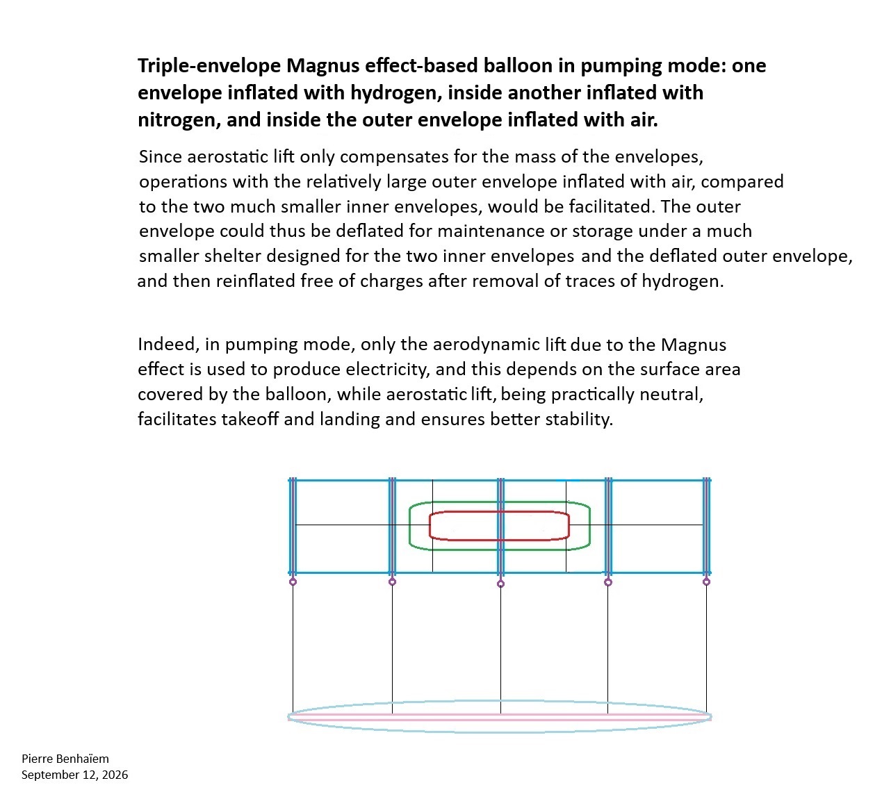
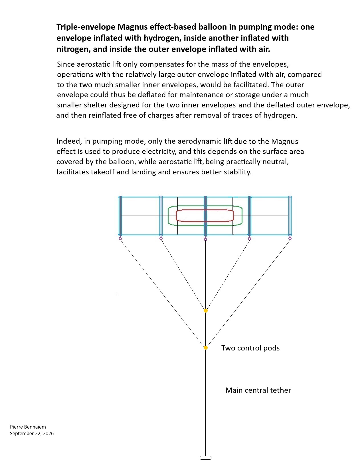
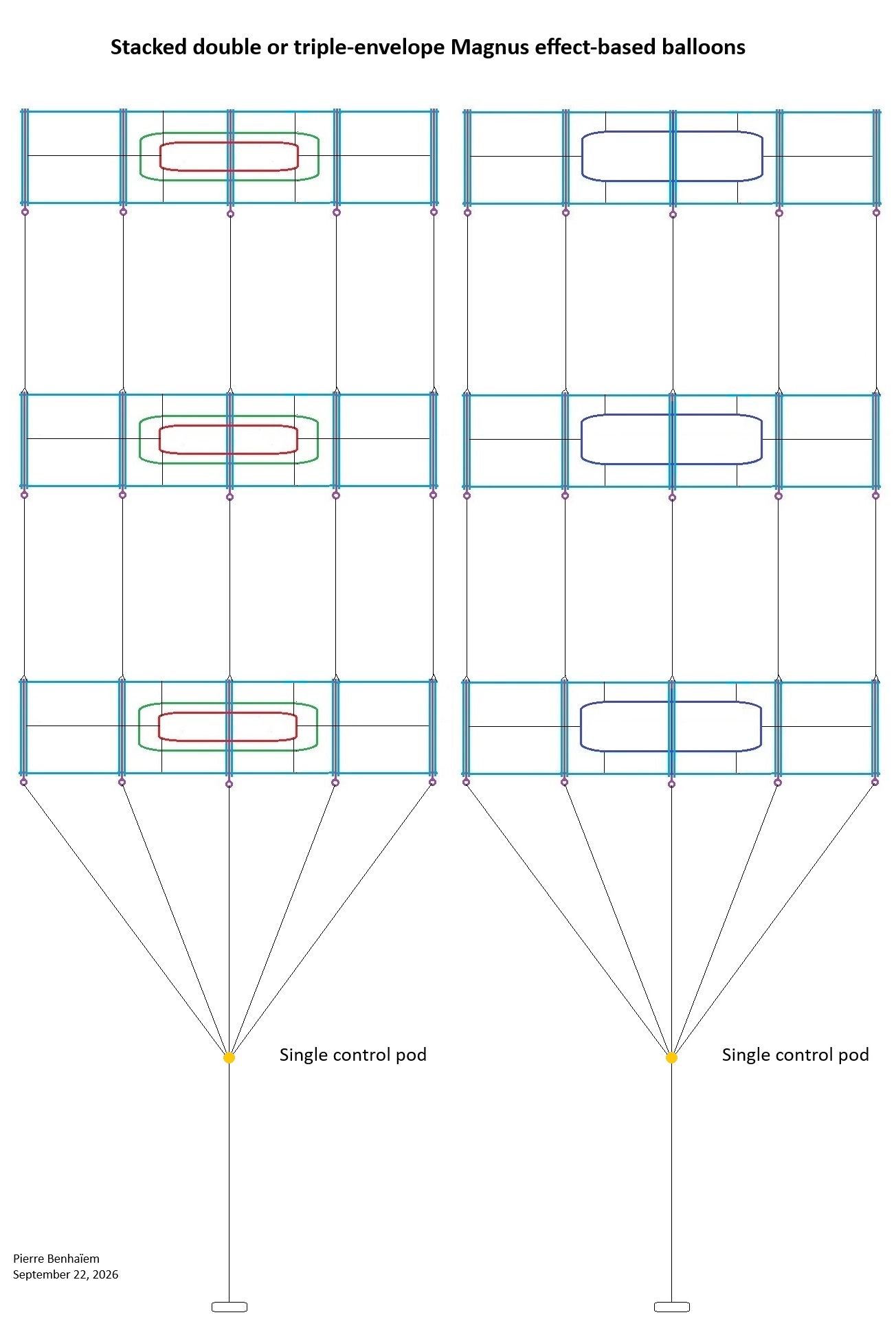
New concept of a triple envelope, the outermost of which is inflated with air, then deflated, then reinflated again…
The outer envelope can be made of ripstop fabric, which is much lighter and cheaper than airship fabric. “The most common fabric used is ripstop nylon with a polyurethane(p.u.) coating to make it non-porous to air” [12]. That said an airship fabric can be preferred to allow still more airtightness, hence higher pressure and rigidity.
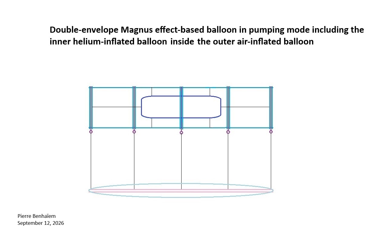
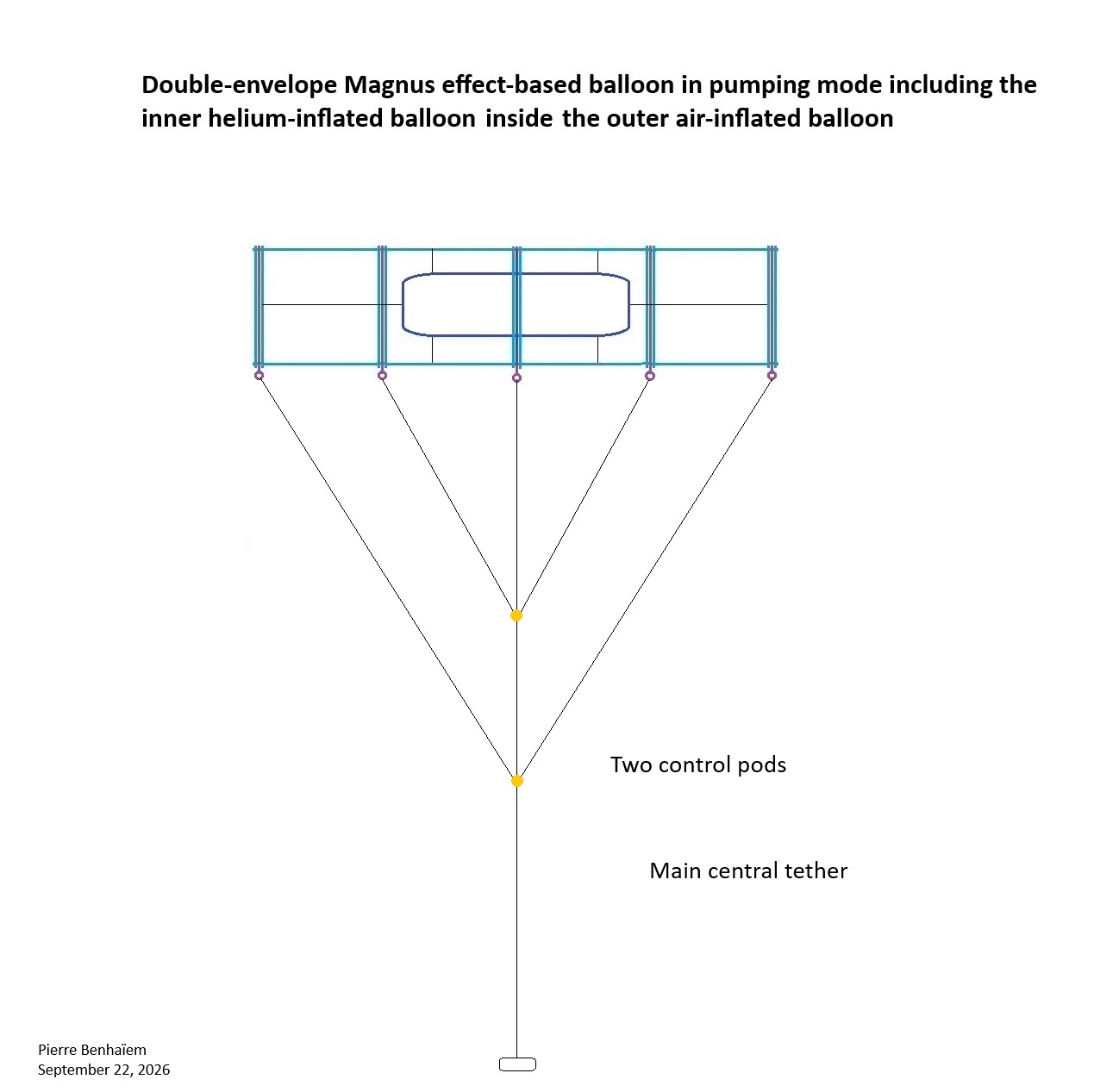
Double-envelope Magnus effect-based balloon in pumping mode including the inner helium-inflated balloon inside the outer air-inflated balloon
Building on the concept and the advantages outlined above of the air-inflated outer envelope, applied to an inner envelope inflated with helium, instead of the balloon inflated with a mixture of air and helium shown in the first sketch.
The corresponding cumulative annual wind energy from LiDAR measurements, shows that the energy available at 10m of altitude, 104m of altitude and 199m of altitude is respectively 0.5 2.5 and 4.7 MWh per m2 per year.
This leads to a complete change in the way wind speed is measured depending on whether it’s near the ground (with AWES performance then overestimated) or at the ABM balloon altitude.
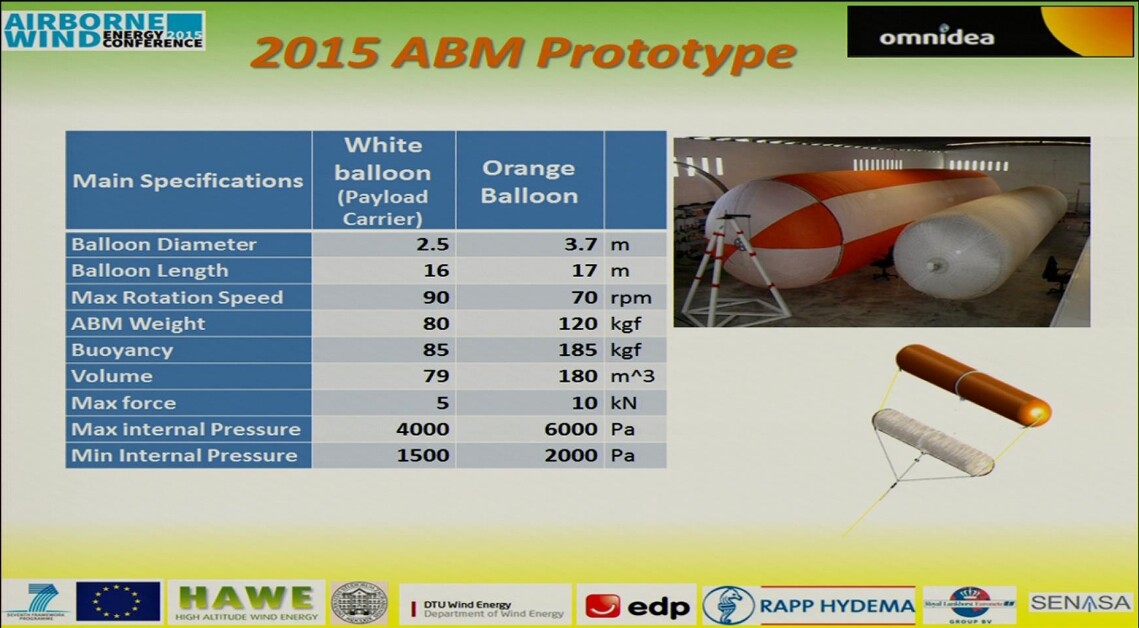
Proof-of-concept and on-field results - analysis results of a representative cycle
Some cycles were performed between the 23rd and the 24th of January 2014 and, cycle number 4 is the cycle which will be analyzed in detail:
-The duration of the cycle was of 70 seconds;
the average cycle height was of 191m;
the wind at average ABM altitude was of 6,23m/s;
In this case the mechanical power produced at the winch is around 1kW, despite a 0,35kW power consumption to rotate the ABM.
About the same “cycle number 4”, a little further:
The magnitudes of the different powers which influence the HAWE prototype during the analyzed cycle are:
• Average power generation, during the power production phase is 2,4kW;
• Average power spent during the recovery phase is 1,4kW;
• The average power needed to rotate the ABM was of 0,35kW, leading to an actual “net” cycle power of 1,05kW (excluding transition period).
(Note: Transition period is always constant and has a high influence on average power depending on the length of the cycle)
These test values were obtained at 5,4 m/s of average wind speed (this average wind is the true average wind throughout the whole cycle), which is clearly below the “nominal design wind conditions” of 8m/s (while standard wind turbines are designed for nominal operation of 10 to 12m/s of wind speed).
As a result, Omnidea’s balloon could be almost as efficient as a flexible crosswind kite at equal wind speed measured at kite height. And we are not even talking about vertical trajectory yet.