The other issue for getting clean data is avoiding feedback wobbling the stack. There is an amount of regen you want, but it’s tricky to get right. And it changes dynamically with the condition of the turbine.
We didn’t have the correct data going into regen control to keep it running smooth. A simple way to think of the issue is, the more regen you put on, the less straight lines are, the more unstable the system can be. + a bunch of other dynamics
Indeed, it is easy to get carried away. Just so people know, all of these “rotary”, “rings”, tensegrity driveshafts, model airplanes flying in circles, etc. have been under consideration by me for decades. I just don’t necessarily spill all my ideas ahead of the fact. Nice to see a few people waking up to some of the vast number of “possible possibilities”.
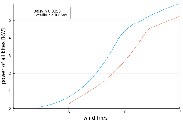
As the W&I Daisy rigid wing is built into TRPTSim I am able to make a comparative plot quite easily. Don’t take this very seriously, both the Daisy and Excalibus must be regarded as very rough sketches at this point.
The Daisy wing has glide ratio 17.3 while the Excalibur polar I’m using has only 13.3. Just take note for the Excalibur I am taking numbers out of thin air, for Daisy I don’t recall where I got them, but they are based on NACA 4412 airfoil and the selected aspect ratio I believe, unknown Reynolds number.
The two configurations are eerily similar in size.
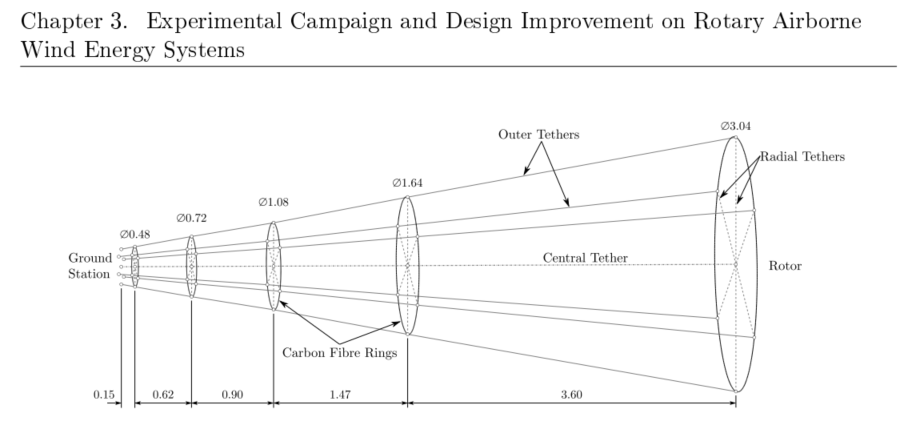
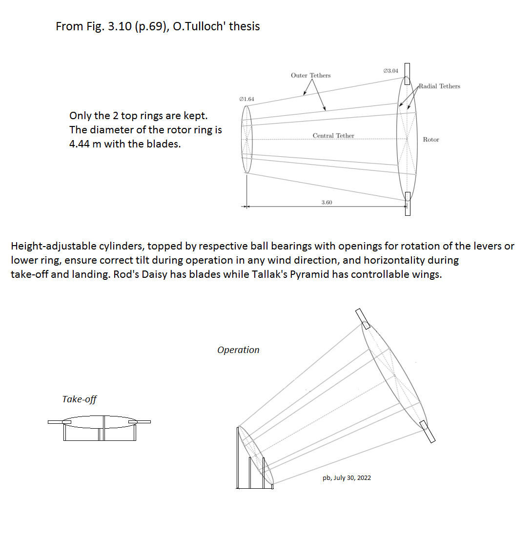
I add a sketch (below) for a rough approximation of a design based on the two last rings, with blades for Daisy, and planes for The Pyramid, more or less following what Daisy has experienced. Many elements are missing or inaccurate, but this is only an attempt. This sketch comes from O. Tulloch’s thesis, Fig. 3.10 page 69, and reproduced by Rod.
By the way I tried to introduce a lower ring rolling on cylinders equipped with bearings or open slides, to get a horizontal lower ring (r0) to facilitate take-off and landing for Daisy or The Pyramid. Perhaps generators for PTO can be settled into said bearings, assuring take-off by rotation as motors; otherwise a central generator-motor does the job. Said cylinders also assure a correct tilt during operation, and are piloted to change their respective lengths according to wind changes.
To launch the kites you’d need to get them above their stall speed I think, so for launch I think it is interesting to look at the stall speeds of different types of kites and how much drag they create at or a little above that speed. For production I think it is interesting to see how fast different types of kites can fly and how much wing loading they can handle. Researching and testing that, and limited testing on how to control them, can be done now already I think, without access to a tower.
Knowing the wing loading a type of kite of your choice is expected to have in different wind speeds can then inform how strong the arms and other elements of your tower need to be for a kite with the wing area of your choice.
Could you say that in this shaft the length of tether between the cartwheel and the kite is equivalent to @Rodread and @someAWE_cb length of tether between rigid elements? If yes I don’t understand why here this is so much longer, or has this much larger l/r. And if yes, or no, and disregarding tether drag, can you make the shaft that much longer by adding that many rigid elements?
While the designs that @Rodread is looking at are more stiff and don’t twist much per section, the Pyramid has only one section but in turn that section is more twisted. So for the Pyramid having no rigid elements is a benefit that one tries to make the most of whats possible within that constraint. The Daisy and so on have rigid elements in the shaft, so there is no point in making the most of each section. You can have the shaft long by adding more sections
I’d counter that with we’re both looking for optimal twist in each section (one or multiple) which enables our most balanced application of mass to improve performance on several metrics. Pure power, reliability, lower drag, improved area, altitude… There’s a large landscape of potential best choices to optimise for.
In the multi section case,
we don’t have to design all of the sections to be matched to perform at a similar ultimate compression level or twist state,… these parameters can be programmatically ascribed by section.
It may be, that a torsionally weak section with high temperature resistant lines and stronger rings is a good idea as a kinda torque fuse.
e.g. If that section overtwist… No problem just overdrive the PTO to untwist and reset to the correct working torsion level.
This triangular bridle also allows you to have two or three tether attachment points instead of one; one to the tower, one to the other kites, or one to both the kite in front and the kite behind. I wonder how useful that would be.
I think this is more of an observation than a proposal.
To distribute the forces (mainly lift) between the kites, and self-compensate the phases during the rotation, so that all the kites work as a rotor?
It would probably make sense to add some cyclic behaviot in this way. Eg on the upstroke the tension in the front bridle is higher than the rear bridle. At the same time a certain roll angle is wanted. So that could maybe be hardwired into the bridle attachment point
If the purpose of these bridles is to set the blades to maintain trianle line tension and smooth blade trajectory around the loop,
We could suppose that one implication of these extra bridles might be - lessening the effort required from control surfaces
I scanned the text again, but on page 3 for example I don’t see something like T_{B}: triangular bridle tension.
I think you need a variable like that, as to maintain kite radius you need a minimum bridle tension. If you have that, and perhaps a T_N : T_B ratio, you could then decide on a minimum roll angle for your chosen \Lambda value, or relative surface area of airfoils not parallel to the plane of rotation.
Am I overlooking something? I don’t think you can rely on centrifugal force only as you’d like to maximize swept area, minimize kite mass, and perhaps get a thinner shaft with something like the trouser mod.
I have this in the simulation. For now I just monitor that the tension is positive. It has always been due to centrifugal force. But at a certain scale or with different geometry you may have to add outwards roll to make sure tension is always more than «slack»
It seems to make sense to me to attach the tether from the ground station at the center of gravity at the fuselage, and the triangular bridle at an extra fuselage at the end of the inner wingtip, and then angle the outer wing down some, adding some anhedral to the plane.
My assumption is that this forces the inner wing to have a zero degree, or close to it, roll angle (be in the same plane, or close to it, as the triangular bridle), and also that you need the anhedral to give the control surfaces of the outer wing a way to act perpendicular to the axis of rotation, with this zero degree roll angle. And you’d use anhedral instead of dihedral to, like @Rodread often says, help expand the rotor.
If you also make this extra fuselage longer, you could perhaps counteract the pitching moment of the wing at the inner wing tip. If you wanted to counteract the pitching moment of the entire wing you would attach the triangular bridle at a longer fuselage at the center of gravity though I think, which would then hopefully reduce the need for an elevator
In the original proposition, roll control of the kites are active continuously. If the tether is not attached at CG, roll control will be affected. But how much and if that is a benefit or problem is hard to say. With a wing tethered at one wing, one option would be to add a vertical wing and then not worry too much about roll control.
In the end I would normally opt for a single wing rather than a combination of vertical and horizontal. But all options are feasible as far as I can tell.
Indeed we could examine the options of the Pyramid, and possibly return to other topics about MAWES.
Is this triangular bridle really necessary? In my opinion, perhaps by removing it we would have less risk of tension variations in this bridle being able to lead to collapses.
We will have a “classic” configuration of tethered gliders which is starting to prove itself. In all configurations, active control is necessary. So why not remove the extra bridle (in spite of the supposed advantages)?