Theoretical drag of a Tether

I like formulas to calculate stuff rater than just doing a numeric simulation. Does anyone have a good description of a calculated tether drag/power loss?

In Uwe Fechners book “A Methodology for the Design of Kite-Power Control Systems pp 26-27” he mentions without any further calculations that the drag constant is given by:

C_{d,eff} = \frac{1}{3} C_{d,0}

Where C_{d,0} is the drag constant where the whole tether is moving at the kite’s efficient wind speed. I also assumed that the tether is moving only crosswind and is straight, and there is no wind shear.

I assume that if the efficient wind velocity is v, air density \rho, tether length l, diameter d, that the tether parasitic drag on the kite is:

D_{parasitic} = \frac{1}{2} C_{d,eff} \rho d l v^2

I also looked up in the “Airborne wind energy book 2.0” the value of C_{d,0} is in the range 0.98-1.8 for AWE purposes.

After doing some calculations on my own I am getting lower values, perhaps \frac{1}{4} C_{d,0} or even \frac{1}{5} C_{d,0}.

2 Likes

The tether drag contribution is also mentioned on the figure 4 page 15 and studied on:

Edit Windy_Skies, removed dead link.

Drag power kite with very high lift coefficient

New links:
https://www.researchgate.net/publication/320742362_Drag_power_kite_with_very_high_lift_coefficient or https://repository.tudelft.nl/islandora/object/uuid:a62018f4-1b41-4ceb-afa1-fecfaf82e2f3

1 Like

Storm Dunker (Best name in AWES) is the authority on line drag!
Chapter 2 of the AWES book 2
Tether and Bridle Line Drag in Airborne Wind Energy Applications
Storm Dunker

Of note.
The relative effects of line drag go down as you need thicker stronger tethers because drag varies with the diameter but strength varies with the sectional area pi x r x r
So in larger systems… line drag is less important.

I’m going to point out the implications for a networked kite turbine, Each rotor layer adds only a very short section of line. So even with small kites line drag is less important in networked kite rotors…
Also as each layer adds to the tension of lower layers, lower lines can be thicker than upper layer lines, thus more efficient use of materials and only the drag necessary for the transmission.

Sorry it’s so rule-of-thumb… One day It’ll be formalised in an equation. I’ve only got FEA and prototype demos at best so far. University of Strathclyde plan to publish more on it soon.

Ive been trying to put down the equations for an exact solution, leading to a really gnarly diff equation set.

The rule of scaling tether is correct, but offset by the fact that a larger wing necarily needs longer tethers to fly, as you could expect turning radius to be bigger for a bigger wing. But it’s still a very positive scaling relationship though. Also factor in that bigger aircraft might have to fly faster to keep afloat, increasing tether drag.

For smaller AWE, tether drag may be significant so an analytical equation would have been nice. But Im not sure its solvable with normal math. Who knows?

1 Like

StormD would agree that tether drag varies greatly with complex factors like variable tension and harmonic length, since “strum” on the line is the max-drag regime.

That said, a numeric prediction capability is adequate for most design purposes, adding a crude fudge factor for strum. Testing remains the final validation of any numeric prediction.

1 Like

This review is of exceptional gravity, as it wants to mislead the authors with a false and unverifiable theory, in short a pure opinion of the reviewer. In fact, in the part that expresses a critique of merit, he states that the performance of an unidentified AWES decreases by increasing the tether length, when exactly the opposite is true, for two reasons: 1) the tether drag cannot change the speed of wing flight, but only and weakly to the pitch. 2) a longer length allows to reach more high and intense wind.
Perhaps this issue hide some personal interest because this remark blatantly conflict with well established flight mechanic science and atmosphere physics, in alternative is a very poor understanding of the matter.

Welcome to the forum, @Massimo! :slightly_smiling_face:

I think the results kind of also debunk the larger kite -> higher altitude. I think it is not necessarily true that scaling the wing or wing area by x will give you more tether than x times the tether you had before scaling.

Or, to rephrase, I think tether length may scale with wingspan or wing area. So there may not be a magic size where tether drag does noe matter anymore.

Welcome @Massimo !
For what I know the review looks to be correct.

Nooooo! Please, a kite behavior like a glider could be described with 3 forces: lift, drag and weight. The case of the kite see the weight replaced by the tether tension. No other differences, the weight thrust the glider as the tether tension do with kites. The tether tension in C shaped kites is always axial, no licit vector decomposition, the link between wing and tether is a 5DOF. This is a classical newbie error or the desperate tentative of the wind industry to undermine tropospheric wind exploitation trough corruption of the well established science, as happen in other sectors. We are preparing a page explaining again the issue but we are very surprised of the widespread poor understanding of the matter.

This is probably relevant:

Yes Luke, thank you, this is very relevant and introduce the key elements of understanding, the difference
with KiteGen is that our tether isn’t linked to the CoM and the tether drag induce only moments (pitch) to our wing, the opposite of Ampyx case. I agree with the paper that tether model is crucial for accurate evaluation, it is the only model that cannot run in real-time despite parallel computing, because of the insane propagation speed of the axial tension forces. The moment imposed to the KG wing stretch asymmetrically the wind power spot and limit the length of straight paths at full power (before the wind angle is too much aligned to the wing chord). But this isn’t an issue because of continuous and cyclical lemniscates, with direction changes (U-turns) well before those derating limits and before wasting too much energy.

1 Like

See also KiteGen Research High Altitude Wind Generation... and also KiteGen Research C-shaped semi-rigid Power Wing. If Massimo’s statement is verified it could be good also for Optimization of a soft wing with turbines aloft as it is also a two lines C-shaped wing.

1 Like

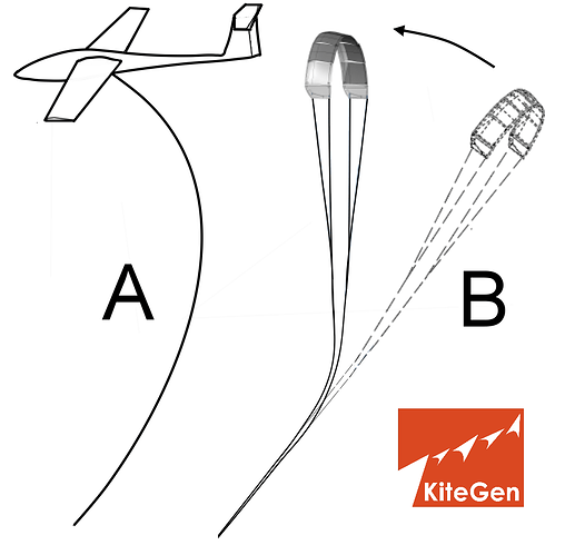
So if figure A is correct we are in agreement as far as I can tell. It should be clear that if the kite/plane/plite is heading directly forwards the tether may be decomposed as a tether force aligned with the lift force of the wing, a tether force aligned with the drag of the kite, and perhaps also a sideforce component not easily seen on a 2D drawing.

So, if we are in agreement so far: The curvature of the tether is linked to the tether drag and the tension of the tether. More tether length with the same tension inevitably gives more curvature in total and the incidence angle og the tether changes so that more force is allocated in the direction of the drag

I’d appreciate being corrected in this if my understanding is inacurate

1 Like

With regard to the paper cited [“A reference model for airborne wind energy systems for…” eq 17] the formula for tether drag is actually cited incorrectly. The original text is in the first “Airborne Wind Energy” book on page 67, eq 4.6. Anyways, this is a fine simplification of tether drag. Though it will not take mass effect into account. The formula should of course be:

T_d = \frac{1}{8} \rho C_T d_{tet} l || v_a || ^2

(the …^2) is missing in the text

(Note that the formula is similar to my previous post with K=1/4)

1 Like

Aye, it’s a fab paper, great research, really neat match to real life and I can’t wait to see it applied to my work. …
However, in the intro to (PDF) A reference model for airborne wind energy systems for optimization and., As ever, awareness of AWES concept space is missing in the text
The two most promising approaches to AWE are the pumping and drag mode
Most promising and most studied are not, in this case, the same thing.
I guess I’ll never change this institutionalised perspective… I will have to admit. . .
Kite turbines are drag mode. Mechanical drag mode rotary kites.

No.
One of the first envisaged AWES was (and still is) Sky Windpower. It was studied to harness jet-stream at several km from the ground level, following or perhaps preceding C. Archer’s prescriptions. But the weight and the drag (even for a stationary system) of such a long electric tether may have been a problem.

After companies investigated crosswind prototypes, shortening the tether year after year, that due to weight and drag concerns mentioned in several scientific publications of which Bas Landorp’s.

However knowledge about the tether drag concern can be still incomplete. So waiting for a KiteGen scientific paper with peer review about Massimo’s statement, and comprising both computed and real measures.

False, systems without CoM force application thus axially aligned to the lines, the tether drag only appear exactly as tether tension both on ground generator and wing sides, the tether drag finally add generating force. The energy wasted by the tether is paid by the reel out speed that is slightly reduced for geometrical reasons and wind spot deformation. This affects production only in very low wind condition when the reel out speed isn’t nominal yet. Look here for the potential buffer in presence of de-rating bound conditions:
https://www.researchgate.net/publication/331312828_KiteGen_Research_High_Altitude_Wind_Generation_Tropospheric_Wind_Exploitation_Under_Structural_and_Technological_Constraints

Line drag cannot be added to the wing drag because it acts axially, like gravity to a glider, without limiting the flying speed, hence the system AE.
The delay that the line imposes to the path in airspace affects only the angle with respect to the wind and is never a degradation, because it only modifies the power spot shape.

This does not at all counter any of the arguments I have previously set forth. It basically just states a precondition for the analysis which is clearly untrue.

To prove it’s untrue: Its not hard to imagine the tether facing in the drag direction, providing only additional drag and no force to counteract the lift force of the wing. (This happens every time the tension is very low and flying speed is maintained)

In practice, the tether points slightly backwards providing the force you describe in addition to an extra drag force in the ditection of the drag. It may also provide a sideforce, but then we are complicating things too much for this discussion.

My advice would be to rethink tether drag and then after having understood tether drag, reread your paper… I think you might need some adjustments.

True but only if the wing goes downwind without crosswind figures. These generate an apparent wind, resulting a higher tether drag without generating any useful force.