Even Chat GPT agrees … 2.2
The drag coefficient of a kite can be calculated using the following formula:
Cd = D / (0.5 * rho * v^2 * A)
where:
Cd is the drag coefficient
D is the drag force
rho (rho) is the density of the fluid the kite is moving through
v is the velocity of the kite
A is the reference area of the kite
To calculate the drag coefficient, you will need to measure or estimate the drag force acting on the kite, the fluid density, the kite’s velocity, and the reference area of the kite. The reference area is typically the frontal area of the kite. Once you have these values, you can plug them into the formula and solve for the drag coefficient.
Note that the drag coefficient of a kite can vary significantly depending on the shape, size, and orientation of the kite, as well as the velocity and density of the fluid it is moving through. It is also influenced by other factors such as the roughness of the surface of the kite and the presence of any appendages such as fins or strings.
I ran the calc
860 ÷ ( 0.5 × 1.2 × 5 × 5 × 26 ) = 2.2
Man I’m cool like @PierreB now
However I just asked the bot to do the calculation and it failed spectacularly at every attempt
I just watched an episode of Columbo, made in 1974. It is mentioned that a main parachute at that time was 60 m², and descended with the pilot at 6 m/s.
Here we speak about rescue parachutes. That said the drag issue could be common for both.
Apart from that, this would pose a theoretical problem for the yo-yo mode here in horizontal use. We know the limit of 4/27 (almost 15%, compared to 16/27 Betz limit) but with such drag coefficients (starting with 2.2) this limit would increase to a little more than 8/27 (about 30%). How is it possible (if at all), knowing that the parachute area covers the wind area (roughly not less, not more), without any crosswind motion?
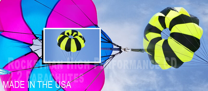
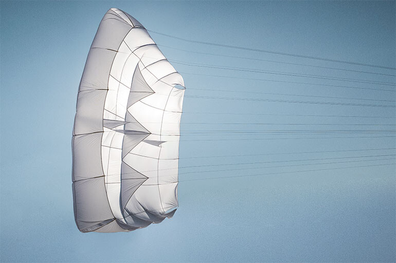
The Yeti UL is a planar rescue, a new type of rescue that offers maximum safety performance in the smallest ever package. It’s our lightest and most compact rescue, ideal for hike ’n fly.
A planar rescue is a new concept of rescue developed in-house by Gin Gliders, made possible by our new anti-billow rib technology. Lines are attached to triangular ribs deployed in a cross shape. This greatly reduces the billow of the canopy and produces an almost flat upper surface. As a consequence, the projected area is increased by 30%. This means excellent sink rates are obtainable with a lower flat area and packing volume. Overall, the efficiency of this new system is the best we’ve ever experienced.
TECHNICAL SPECIFICATIONS
SIZE
S (19)
M (23)
L (27)
Surface area (m2)
19
23
27
Weight (kg)
0.87
0.99
1.17
Packed volume (cm3)
2025
2475
3006
Sink rate (m/s)
5.3
5.2
5.1
Maximum load (kg)
85
100
120
Certification
EN 12491:2015
EN 12491:2015
EN 12491:2015
Drag coefficients become XXL: 2.65 for S (19), 2.68 for M (23), 2.85 for L (27) if I am right.
Study of parachutes is very important in aerospace industry. In this research, the effect of various Reynolds numbers on a parachute with a vent and without a vent at the top on drag coefficient in a steady and turbulent condition is studied. After a complete research on an efficient grid study, the drag coefficients are calculated numerically. The Reynolds number is varied from 78000 to 3900000 (1 m/s to 50 m/s). It is found that, for a parachute without a vent at the top, as the Reynolds number is increased from 78000 to 800000, the drag coefficient is decreased from about 2.5 to 1.4, and then as the Reynolds number is increased to 1500000, the drag coefficient increased to about 1.62 and it stayed constant for higher Reynolds number up to 3900000. As the vent ratio of the parachute is increased from zero to 5 percent of the parachute inlet diameter, the drag coefficient increased and for further increase of the vent ratio diameter, the drag coefficient decreased, but the general variation of drag coefficient was the same as of same parachute with no vent.
The question is; when traditional windmills fight to have a lowest possible drag, is high drag something worth spending tine on? And even with some changes in drag coefficient, is it really worthwhile to spend effort to get than additional x% increase in drag vs just increasing the wing area the same amount? I have a feeling this is a dead end…
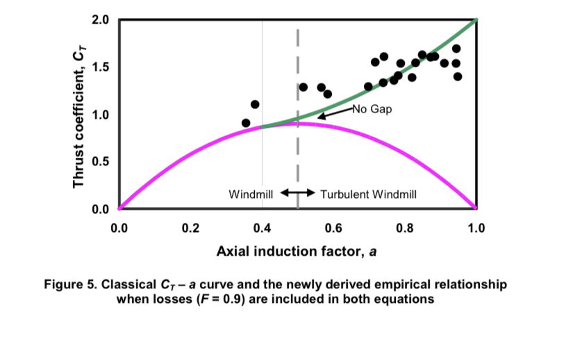
But, for the sake of having started this discussion. A windmill has a «thrust coefficient» of 8/9 for an optimally running windmill. If we regarded the swept area a parachute this number would be the drag coefficient. Maybe changing parameters could yield a higher number, the formula is
The planar rescue parachute could be a logic possibility for the reeling (yo-yo) mode: high drag for a swept area dragging downwind. With such high drag coefficients and such lightness, no need for complex and risked crosswind kites which use more space than required and are already dead ends.
That said a suitable bridle (and also some ballast), should be implemented in order to provide some lift (and also stability) until a sufficient (but not high) elevation angle is obtained, keeping a thrust at least equal to the initial drag. Now if an equivalent lift coefficient (about 2.8) could be achieved, things would be still better. Moreover aligned (not crosswind) squares could perhaps be stacked by their respective sides in bumper car mode. Work remains to be done on the depower system.
@tallakt , this point looks to be interesting. Please can you detail the formula and provide a link for the book, if it is possible. Thanks.
To tell the truth, I had never imagined that surfaces could have a drag coefficient of the order of 2.5 or even 2.8. I don’t think that a coefficient of more than 4 would be possible though, as this would mean overstepping the Betz limit, and by using yo-yo mode…
You’re likely not right, or the information given wasn’t, as the maximum drag coefficient for a parachute, or any object, that I was able to find was 2.5. If the given surface area is also not equal to projected area you also couldn’t make this calculation as you need the projected area.
Also with the “almost flat upper surface,” the parachute likely deviates from the optimum shape for maximum drag.
I don’t know about parachutes, but often for them glide ratio is not 0, so that, through lift, may contribute to a lower sink rate, so then you can also not use sink rate in your calculation for drag.
We didn´t just match a few existing systems together, no we developed a complete new rescue system. Not only the shape is new, but also its mode of FUNCTIONING. Immediately after deploying and opening of the canopy, the X-TRIANGLE sinks vertically and does NOT generate any FORWARD MOTION. The canopy is FULLY SYMMETRIC straight after the opening. There is no pre-brake like on a rogallo canopy.
The pre-brake on a rogallo brings just a little slow down of the forward speed and definitely NO slow down to zero speed. A rogallo rescue is already from the construction side build asymmetrically and has always a GIVEN FORWARD motion, without this motion the rogallo would stall like a paraglider.
Rescue parachutes often have a symmetrical shape: they are not wings. The sink rate is therefore on a vertical basis, as indicated above. Consequently, the calculation of drag as I have done is possible.
It is a reason why for this “planar rescue” drag coefficients are higher. That said drag calculation would be more precise by using the projected area beside the surface but I don’t have both data for the specifications of the rescue parachutes I examined, although a video indicates a flat area of also 19 m² (at 0:07) for the Yeti UL, S(19).
The video and diagrams show a projected area a little less than half (about (\frac {2}{3})^2) of the flat area, which if sink rate was all due to drag, would result in more than doubling of the Cd, so a Cd of over 5, which is more than double than that of any object I am aware of, so there must be a mistake somewhere.
Terminal velocity: V_t=\sqrt{\dfrac{2mg}{\rho AC_d}}, rearranging for the unknowns: AC_d=\dfrac{2mg}{V_t^2\rho}. Inputting the known values for the middle parachute: AC_d=\dfrac{2\cdot101\cdot9.8}{(5.2)^2\cdot1.2}=60. Assuming sink rate is all due to drag and Cd is 2.5 gives you a projected area of 60/2.5=24m^2, which is more than double the given projected area.
Perhaps it is interesting to look at sink rates and drag coefficients of different parachutes a bit more.
I bet buoyancy plays a role, and lift in other types of parachutes.
In the end of my comment above I referred to the rescue parachute Yeti UL, S(19), mentioning that the video indicates a flat area of also 19 m² at 0:07. I am linking again this video (from the manufacturer Gin Gliders):
So at 0:07 seconds from the beginning, you can see the mention: Yeti UL flat area 19 m² and other specifications. I guess that flat area = projected area. So the whole area of the parachute is higher than 19 m². Otherwise the projected area would be still more tiny, leading to an unrealistically high drag coefficient.
That said the website specifies for the same model Yeti UL: S(19) Surface area (m²) 19 without specifying whether it is the flat area. We see a bit of curvature (much less than for other parachutes, hence its better sink rate for an equivalent whole surface) and above all almost vertical edges which add surface. So I think 19 m² is the flat area as specified on the video.
There are certainly things we don’t know about how to increase the drag coefficient, such as airflow or various aerodynamic effects.
Apart from this some training-chutes are used for sports (link from Joe Faust):
A little more effort, a little lift for the high drag coefficient parachute(s), and you get a reeling AWES with one or more very large surfaces…
At 0:08 in that video if you look down you see the two squares for each parachute, the smaller one is the projected area, the bigger the flat area. If you also look here Yeti UL - Planar rescue parachute | Gin Gliders on the table, it says surface area, which is equal to the given flat area. Also a bit lower down:
So flat area = surface area. Because the projected area is relatively larger you can get away with a lower surface area to get an equal projected area and so a lower weight and packing volume of the parachute.
Indeed I just saw: “the two squares for each parachute, the smaller one is the projected area, the bigger the flat area”. And if you enlarge the video capture, you can read for the first parachute (Yeti UL), flat area (pointing to the bigger red square), projected area (pointing to the smaller dotted square); and for the second parachute (conventional rescue), difference between flat and projected area, with a smaller dotted square of the same dimensions (?) but a much bigger red square.
I also get approximately 5 for the Yeti UL (the planar rescue) by roughly estimating the projected area (a little more than half of 19 m², so about 10 m²) and counting the squares on top, of which there are 25, those on the edges being slanted, plus the vertical rectangles forming the edges around the perimeter.
The other parachutes in the range have a larger surface area for the same projected area, so the drag coefficient would be approximately the same at 5.
5 is an incredibly high value that seems impossible, and at the same time these parachutes seem to be incredibly small compared to their respective users.
I wanted to know more by asking the manufacturer with a mail: he indicated that some of the data is not in the public domain. I assume that to get a Cd of 5 (if it is the correct value), a lot of aerodynamic work had to be done.
I think that for a reeling (reel-in / out = yo-yo) AWES such surfaces could perhaps have an interest if a little lift allows them not to touch the ground, and knowing that high altitude winds would be approached by enlarging the surfaces (just as for traditional wind turbines that reach higher altitudes as they grow) or by stacking them.
Apart from that, I just tested one of these parachutes below, getting about 6 N with a more or less 2 m/s wind, then getting a maximum thrust of 20 N (I will try later with stronger winds and an anemometer) by trotting against this wind. Specifications on: https://www.amazon.fr/dp/B07XGJCB7F?psc=1&ref=ppx_yo2ov_dt_b_product_details
I think 57 inches x 57 inches (1.45 m x 1.45 m) as shown on a photo, perhaps would lead to a projected area of about 2 m² which seems higher than the real projected area (1.5 m² ?). I measured its surface area at about 2.5 m².
See also the video about “Increasing Parachute Drag” (curve at 2:05, Descent Rate Comparison (Normal vs Reefed)) and the explains below:
A high drag coefficient (Cd) rescue parachute used as a yo-yo kite, flying at a low elevation angle, could look like this (Globe Light - Dudek) :
Or even (still lower elevation angle, but more vertical parachute (higher angle of attack):
Here the lift is only useful to prevent the kite from dragging on the ground or (for gigantic dimensions or by stacking parachutes) to avoid to catch people working on the site or to pull up trees. Even with a low angle of elevation, the parachute(s) can extend far enough to harness a large vertical frontal airspace including low and high altitude winds, a little like current wind turbines with their vertical rotors.
Besides that, we were talking about drag coefficients for rescue parachutes of maybe 5 for the square ones, and I would say a little less than 4 for the round ones, but without having the data, proceeding by more or less exact extrapolations.
The table below shows our measurements done over a period of 5 years to accurately determine the coefficient of drag (Cd) of the Iris Ultra Parachutes.
All tests were done having measured the weight of the rocket accurately upon landing. In addition we had precise information on the parachutes themselves and used altimeters to log the data. Factors that affect the coefficient of drag are altitude, barometric pressure, air temperature, and humidity. The factors listed here, given that altitude stays constant, can vary the Cd by up to 20%. Fruity Chutes rating of 2.2 Cd is considered to be very close to the worst case that we had measured over many flights.
Fruity Chutes Iris Parachute Cd Performance Log
Rocket, Drone, or Company
Who
Chute Used
Date
Diameter (in)
Recovery Weight Lbs
Descent Fps
Calculated Cd(frontal area)
Mag Max
GE
IFC-72
4/1/2011
72
15.53
15.05
2.103
Mag Max
GE
IFC-60
5/20/2011
60
16.1
17.9
2.219
Comp 4
GE
IFC-72
5/21/2011
72
23.3
16.95
2.487
Mag Max
GE
IFC-72
6/12/2011
72
15.6
13.667
2.562
Comp 4
GE
IFC-72
4/7/2012
72
22
18
2.083
Comp 4
GE
IFC-72
5/19/2012
72
23.6
16.85
2.549
Comp 4
GE
IFC-72
6/16/2012
72
23
16.75
2.514
Not sure
DR
IFC-60
7/20/2012
60
16.8
18.5
2.168
Max Maxx Thunderdome
GE
IFC-72-ZP
1/2/2016
72
19.025
13.97
2.990
MN Drone
Ido
IFC-66-SUL
1/22/2016
66
13.78
14.57
2.369
MN Drone
Ido
IFC-66-SUL
1/22/2016
66
13.78
12.66
3.138
MN Drone
Ido
IFC-66-SUL
1/22/2016
66
13.78
13.06
2.949
MN Drone
Ido
IFC-72-SUL
1/22/2016
72
13.78
12.7
2.620
MN Drone
Ido
IFC-72-SUL
1/22/2016
72
13.78
11.45
3.224
MN Drone
Ido
IFC-72-SUL
1/22/2016
72
13.78
12.57
2.675
MN Drone
Ido
IFC-72-SUL
1/22/2016
72
13.78
12.04
2.916
Mag Maxx Thunderdome
GE
IFC-72-ZP
2/6/2016
72
19.025
15.6
2.398
Average Cd 2.586
I noted a Cd of 3.224, and for drone recovery. The rescue parachutes for paraglider pilots mentioned earlier may have even higher requirements and seem to have a higher Cd.