Then what are “secondary effects (to) scaling Wing Span”, if not Area by AR?
To understand me, understand the basic claim that highest-power-to-mass is the most predictive scaling advantage, and the soft power-kite has highest-power-to-mass of any AWES wing. Area, AR, tether numbers; all such are secondary factors.
You write-
“(Scaling Law) rules apply to soft or rigid kites equally.”
Not true. Rigid airframe structure suffers more in scaling under Galileo’s Square-Cube Law.
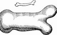
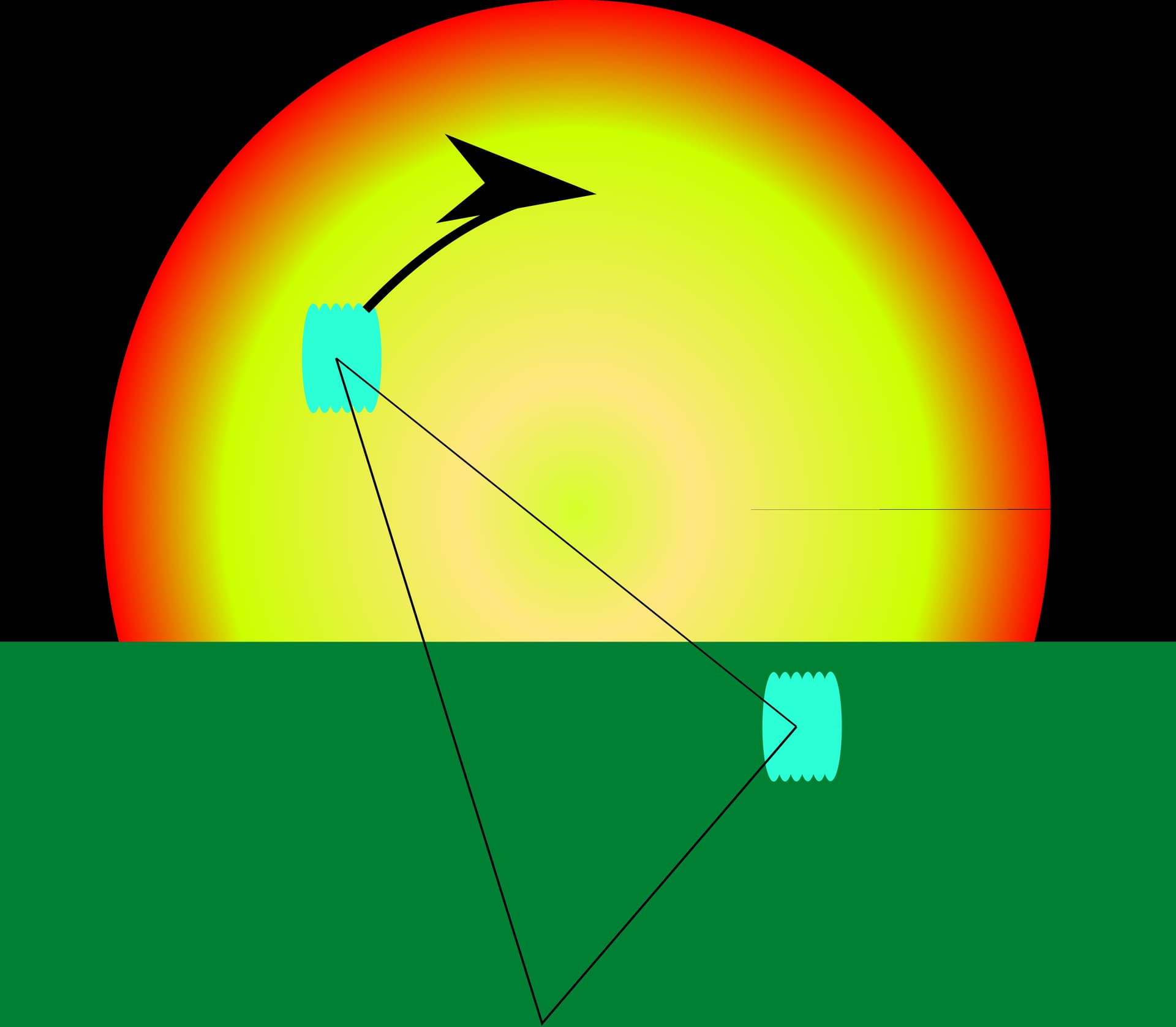
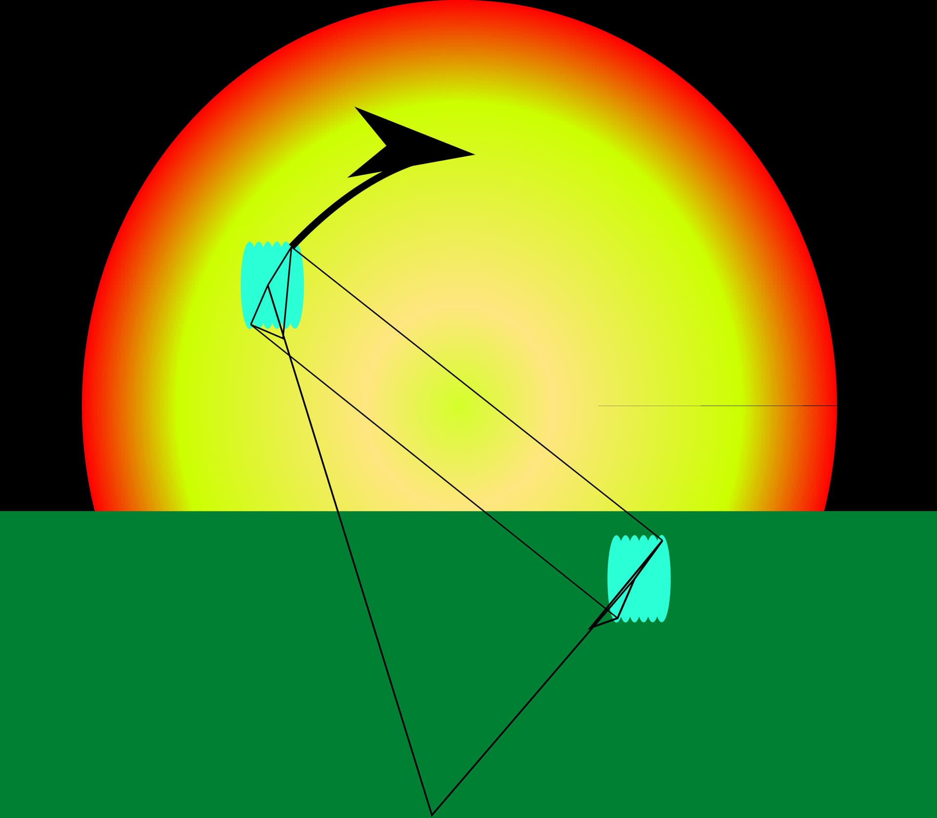
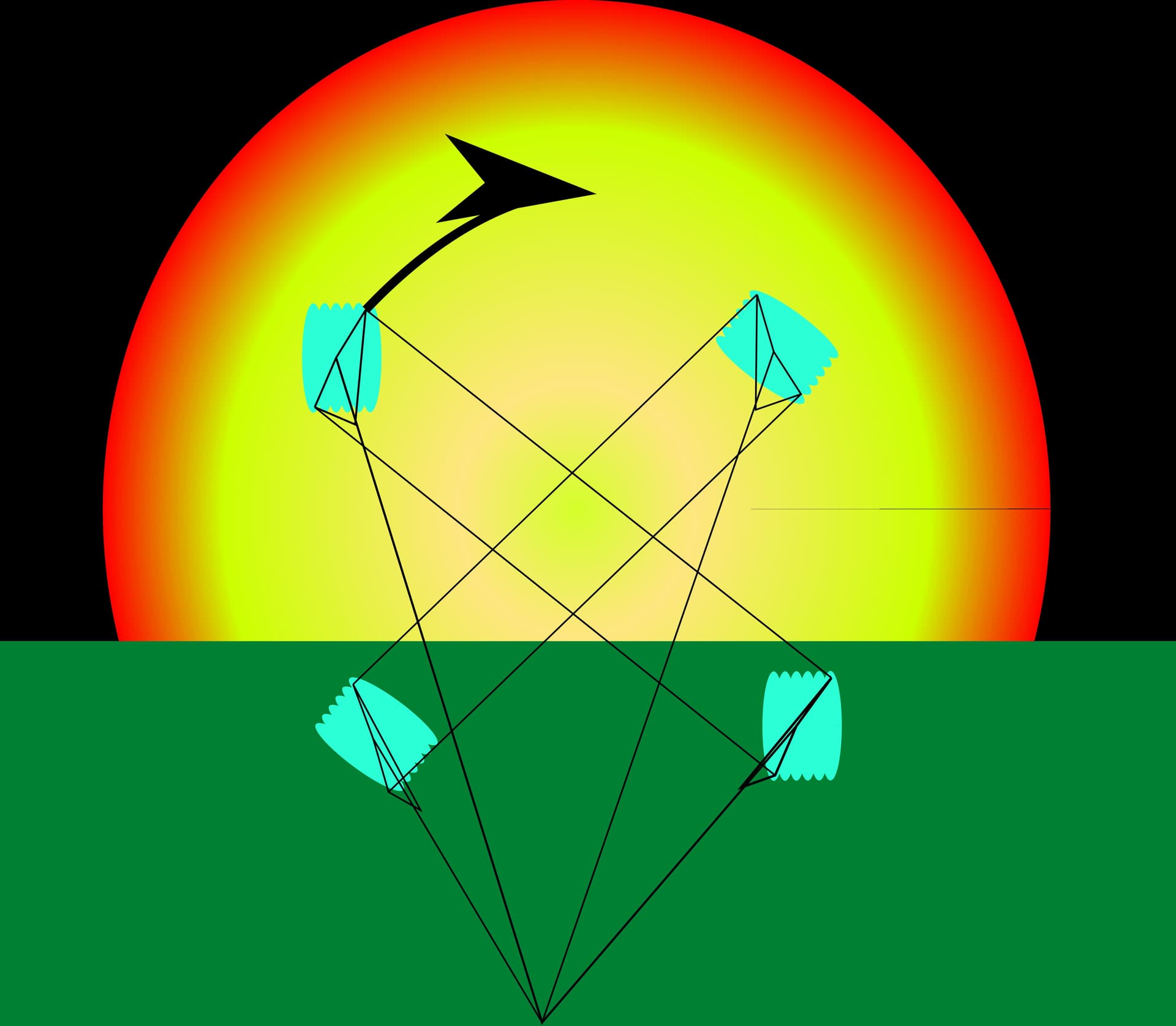
For Pierre, regarding whether one can simply extrapolate a 3D kite geometry to scale up, here is Galileo’s original graphic-
So A is neither a primary nor secondary effect of WS to you? Only conductive tethers can build up heat problematically, by scaling up. The largest pure polymer hawsers in the world stay about as cool as toy kitelines, by mechanical force super-conductance efficiency.
Note that dimensionless wind velocity within the same (FAA) airspace limit allows larger lower AR wings to have lower Re.
What is a “better” Re to you? Most aerospace engineers simply optimize to whatever Re the problem offers. The inherent Re regime of giant AWES kites is not “better” or worse, unless a kite must sweep fast just to stay up.
Indeed I should have clarified that flexible AWES could scale like sails, undergoing a lesser mass penalty, then benefiting from a lesser cut-in wind speed. But this is well known.
Reynolds numbers which are more beneficial to AWE?
Aerodynamics is not my speciality. I have been told that a larger wing will have a reynolds number to give it slightly better lift… anyways, a good example of a secondary scaling effect, whether good or bad in effect
I dont believe soft kites are not subject to «cubic mass scaling».
A larger piece of cloth must be thicker to maintain its strength in larger wing areas. Perhaps you can scale for a while using a constant fabric thickness Eventually it will be as thin as is possible to produce, and with the next scale, I assume the fabrick thickness must scale as well. Same goes for line weights and such. One would have to analyse each part by itself to be sure, but I would be surprised if this was not true.
You could perhaps add more bridling in larger designs (and thus save weight), this would be a design change.
Soft Kites are definitely Square-Cube limited, no one claims otherwise. Panel fabric can remain thin while load-path network must grow in relative mass. The good news is that Soft Kites still scale far better than anything else, while inherently more robust than Rigid Wings.
Thus Soft Kites are proven to 1000m2 Area and beyond (MegaFly, X-38, Osborne, Lynn), while far smaller rigid kites are marginal performers that crash irretrievably (Gigant, M600). Crashworthiness is a serious scaling factor too, even if just viewed from an economic perspective.
I don’t believe to have mentioned that “soft kites are not subject to «cubic mass scaling»”, but rather are “undergoing a lesser mass penalty”.
The link for the paper below explains how the mass penalty can be for a ram kite. https://www.researchgate.net/publication/290775361_Ram-air_Wing_Design_Considerations_for_Airborne_Wind_Energy page 532:
" A prime example of the scaling process is documented nicely in the X-Fly family
of Ram-air precision cargo delivery systems from Airborne Systems North America
[9, 11]. The development originated as an Advanced Concept Technology Demonstrator
research program from Natick Soldier Systems, whereby iteratively heavier
weight requirements were levied (0.25 ton, 1 ton, 2.25 tons, 4.5 tons, 13.5 tons, and
finally 19 tons). The wing sizes were 36 m2, 102 m2, 250 m2, 350 m2, 900 m2,
and 1,040 m2, respectively."
Scaling by size would allow to avoid the risks of mess or collision of numerous unities or elements that are not constrained when the winds are capricious. A giant single rotary AWES using numerous rigid thin and light blades with a lesser risk of collapse could be realized if its structure of which the bridle is well studied.
On the Old Forum a “Metakite” was defined as a “kite made of kites” network; a true “scaling by size” unit. The sub-kites could well be around 200m2, and the meta-kite comprised by hundreds of these.
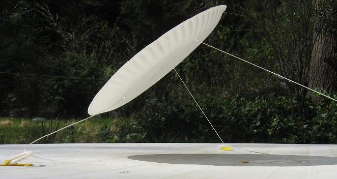
An Isotropic kite like @kitefreak’s (see below) can have several spaced anchors, and can use the earth as spar according to a good principle from DaveS. Can this property allow the kite to scale more? For what I think, pros are: earth as spar, spaced control of the kite, but cons can be the inability to implement (example for a parachute) devices such as nozzles or side openings to stabilize the parachute as found for parasailing.
This project will: 1) define and model design configurations of both Fly-Gen and Ground-Gen systems at single-unit device capacities of 7, 15, and 30 MW, 2) simulate power production operations through methods ranging from first-principle science to in-house software KiteFAST to identify, quantify, and assess all capacity-limiting phenomena and identify the potentially superior max capacity technology.
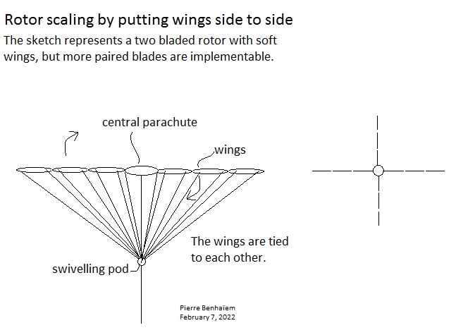
Scaling by size and Scaling in numbers rather than size could be gathered together, above all for a rotor like on the sketch below, by simple attachment of the wings to increase the wingspan without having to implement too large units, achieving a networked AWES with structural cohesion:
I thought about tied wings also for a crosswind AWES, but they are better for a rotor, because the relative narrowness of the blades is compensated by their number in order to fully sweep the wind area, and this without affecting the cohesion of the structure which could function without automated control (although all the same implemented).
The structure on the sketch is achieved by tie additional wings for the two-bladed rotor on the video below; when it becomes very large some additional paired blades are added.
By tying GigaFly (60 m span) each other, gigantic wings could be achieved: a sort of networked kites but mitigating the risk of entanglement.
I think you are correct @PierreB
There is nothing about network kite designs
Such as the rotor you propose or other Network Kites and Daisy network kite rotors which prevents the driving elements of a rotor scaling… as long as they can fly reliably.
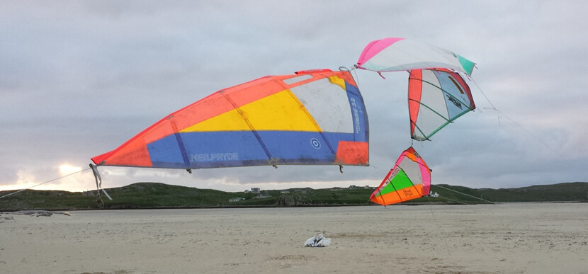
The gigafly and mega fly modular parachutes which use multiple units side by side could be a good guide to establishing super wide multi unit kites.
Wide tethered kites are stable whether the elements are large or small
apologies I don’t remember the correct accreditation for the following photo
in regards your multi-kite rotor drawing.
Yes multiple elements side by side is a great idea as you increase stability and scale with better aspect ratio for higher L/D. All good but I think it can be improved…
Maybe you don’t want the 3 central elements ( central parachute and 2 kite wings)
Nor the 2 outer wings. As they look to be too far out
Just numbers 2 and 6 out of 1,2,3,4,5,6,7 as shown
3,4,5 will be less efficient as they don’t sweep so far and they block flow - axial induction.
1 & 7 are too far from the power zone (just an effect of the drawing… yes really we want more kites side by side)
On longer bridles 1 and 7 become viable… The relevant metrics are the angle of the blade from the power zone and elevation of the rotor
Given controllable wings - you don’t need rigid rotor outer ring parts - Tensile alone will do. Rigid is really only there for launch and land in my builds
The proof of this is that a single 2 line kite can always fly out of the power zone in any direction.
With the sort of scaling you are suggesting … huge!!..
yes, As large a parachute / kite as we can make can still be tied side-to-side with it’s twin…
and still have room in the sky for a twinned (or even multiple) rotor blade configuration to operate on long tethers
For a twin pair of kites configured to work by spinning against each other …
Launch from the ground may be simplified if one kite can first be pulled into the air (by drone) such that it self inflates like the mega fly and released about 9-o’clock, well within the wind window so that it can … then be steered clockwise to 10, 11, 12, 1, 2, 3…
Such an action could pull the twin kite into flight to start working as a rotor.
3 kites like this makes a huge stable rotor
for each blade an element of anhedral bank helps to maintain tension across the whole x structure
(outer tip closer to ground than centre)
I’m kinda sure - This anhedral also has the effect of slowing down the cross blade spanwise flow of air therefore we avoid the more extreme vortex shedding.
Sure, but I think the central part, of which the central parachute, is there to provide both a structural cohesion and lift (by cyclically varying the suspension line length with the swiveling pod), removing the usefulness of a lifter kite which will be a serious issue (double installation) when the whole scales up.
I don’t think because the whole is like a single wing of something like a RotoKite, knowing said wing is divided in several wings in order to scale more. In all cases the part close to the center goes slow, while the external part goes fast.
I wonder now how the power take-off (PTO) can be achieved, knowing that the diameter could exceed 1 km. Fly-gen by using the last and faster and likely more efficient respective wings? Daisy torque transfer by tensile rotary power transmission (TRPT), what could be the diameter of the ground installation?