It does not make sense to look at the past then draw conclusions about AWE. AWE is still in its infancy. Any discussions are better based on sound argumentation. The document I wrote about «The Pyramid» should answer your questions. Though I don’t have a need to prove anything. I am just sharing in case others may find it interesting
1 Like
Thanks @tallakt
Brilliant job on the Pyramid BTW
Plenty altitude, scalability and rotary transmission. All presented neatly in reasoned calculation.
Reassuring and refreshing for this thread, where a depressing amount of repetition of debunked ideas and denial of fact has become too common.
One more point of interest in this thread which seems to have been overlooked
Length scaling of a TRPT shaft is by modular addition of pattern elements
So it’s mass scales directly with length not cube of length.
See /cb’s various flown Open Tensegrity Shaft Lengths.
And the optimisation calculations Ollie performed on the Daisy Kite Turbine more than doubled the spacing between the polygon ring elements - the system can be significantly lighter per meter. (wouldn’t work well with fairing or be so reliable at those lengths though)
Oh fairing lines - another massive advantage to having multiple short line sections
It’s time to get out of all sorts of dead ends regardless of the variants considered. There are a number of architectures to work on. Let’s not waste time on devices that are not intended to reach the high altitudes required, and which would therefore (in the unlikely event of their emergence) find themselves in very unfavorable competition with HAWT.
I think it very unfair to insinuate about dead ends when sensible options have been presented. The requirement of high altitude is also something you personally came up with. High altitude is not a prerequisite for making reasonably priced power, just an element in the bigger picture
Just so everyone knows the score so far:
There has been no independent replication of any test or analysis showing a height limit to TRPT systems presented in this thread.
There isn’t one citation from any academic institution of even the lowest prestige to discredit the potential of TRPT in this thread.
Plenty of data has been presented on the potential benefits of TRPT AWES.
Yet one poster has repeatedly tried to steer this conversation to claim TRPT are doomed.
Oh yeah, keep it coming
Indeed, a little practical work then. I’m going to take back some elements to facilitate the reading.
Page 227 of the thesis:
Rotor radius 2.22m
Blade length 1.4m
TRPT radius 0.5m
TRPT section lengths 1.25m
Elevation angle 18.5◦
TRPT total length 190m
Tip speed ratio 3.5
Table 5.12: Proposed Daisy Kite System
Design
This results in an operating altitude of 60m
The required lifting kite area is not specified.
Before using the above calculator, we will make a very rough evaluation of the Cable weight per unit length (kg / m), knowing that we have a ring of 0.5 m radius every 1.25 m, and the tethers: let’s say 0.3 kg / m. It is very easy to change this value. We will now assume that the cable tension (by the thrust of the rotor) is 300 N. This value can vary widely depending on the wind speed, which will change the TRPT shape during operation.
Now the most important point: Straightline distance, that we will assimilate to the TRPT total length of 190 m, compared to the length of the initial TRPT of 10 m (to simplify).
For the Straightline distance of 190 m we assume that the two ends are like on the given model before one end is lifted at 60 m altitude by the lifting kite. The same for Straightline distance of 10 m, but before a lesser altitude.
Straightline distance: 10 m
The displacement cable will sag 0.12265 m .
That is, almost nothing as expected. Page 66 of the thesis; “lifting kite with a surface area of 3.2 m²”.
Straightline distance: 190 m
The displacement cable will sag 47.56582 m .
That is 387 times more, while the length is only multiplied by 19.
47 m of displacement cable sag, this means that the TRPT must be almost entirely below ground: it is not possible of course but this gives an idea of the extent of the problem. I can’t imagine the required quite huge lifting kite area to achieve an operating altitude of 60 m as specified. This could lead to further study if we really see a need for it.
@Rodread you did not answer my question, which was repeated several times, of the required lifting kite area, although once and only once, you answered something vague:
What does “same size” in m² mean?
Page 66:
The single skin, single line, lift kite used in the Daisy Kite design is a lightweight lifting kite with a surface area of 3.2 m².
I can’t imagine that you can believe that with a lifting kite of “same size” of 3.2 m², you will lift a 190 m long TRPT at 60 m high.
And in the given example, the rotor has the same diameter as initially.
Re-edit for the second performed preliminary analysis:
In the first performed preliminary analysis specifications comes from the thesis, page 227, as quoted above. It can be seen that the radius of 2.22 m of the single rotor is the same as initially, but the TRPT section of 0.5 m of radius has been considerably lengthened to the given value of 190 m.
Now we will perform a second preliminary analysis by changing some parameters, increasing the number of rotors to 14 (so the expected kite area will increase in proportion in order to allow the TRPT stacked rotors to reach 60 m altitude), spaced 13.875 m apart, and covering the last 180 m, the first 10 m being assigned the initial 0.5 m radius section. The value of 0.3 kg / m will be kept for the whole 190 m.
The cable tension (by the thrust of the rotor) was 300 N, which can correspond to a wind speed of about 7 m/s. Now it is 300 X 14 = 4200 N. Answer of the calculator:
The displacement cable will sag 3.16314 m .
This is much less than before, but still a significant value. If the wind drops to 3.5 m/s, so the cable tension becomes 1050 N, answer of the calculator:
The displacement cable will sag 12.72280 m .
And if the wind drops completely…
That leads to a difficult control to say the least.
Due to their thrust the rotors tend to be horizontal in the direction of the wind. On the video of a TRPT the lifting kite is powerful enough to lift the rotor as long as it is not rotating. But when it does rotate, we see it (as well as at 2:15) coming down clearly under the effect of its horizontal thrust. On the other hand, on the video of another torque transfer device whose one end is mounted on a pole, we see the bottom of the catenary curve (which seems to be slightly below the level of the pole), going up, to be also at the horizontal (see also from 11:13), except for the rotors close to the balloons. So, by seeing the videos, I don’t think these rotors produce significant lift, which is mainly devolved to the lifting kite.
Now Rod, what is the estimated power limit (kW), under applicable mass-scaling multiplied by catenary sag effect laws, for a practical and economic single-unit TRPT AWES?
1.5kW
That’s the limit Pierre
You can’t build a bigger single rotor kite turbine than 1.5kW
It’s impossible.
Please snip that sentence and quote me on it in 10 years. It’s exactly the same one heard thousands of times in wind energy design offices across the world over the last few decades.
You’re right
The optimised trpt system proposed in the PhD calculation is unworkable. It wouldn’t be very unstable with those gaps. It would be nowhere near as heavy as you suggest.
This whole argument is pointless however
There is no point in just lengthening the TRPT as a way to scale the power of a kite turbine.
That’s just a nonsensical proposal.
It’s the same as
How big a tower can we build to put a 1kW turbine on top?
No point asking. Will never be built.
Kite turbines scale with numbers of rotors.
Lifter tension scaling will also happen in numbers and with rotation.
@PierreB your number one bugbear used to be land power density of AWES. _ I agree with that as a priority.
But it contradicts having altitude of a single rotor single shaft system as an AWES priority.
AWES can outcompete HAWT on this measure see https://lirias.kuleuven.be/retrieve/658988 Thomas Haas on Simulation of airborne wind energy systems in the atmospheric boundary layer Suggesting densities of 28 MW/km2. Of course we don’t need to go that high … And I’d love at this point to provide the link to the presentation video by Moritz Diehl from this years AWEC where he showed a rotor farm scheme with an even higher energy density….
A post was merged into an existing topic: Questions about Moderation
Yet you have claimed this now called “nonsensical proposal” on three successive comments.
I only repeated the data mentioned by yourself on the third one from the same source (thesis, page 227), as it highlights the catenary sag effect penalty by “lengthening the TRPT” (your terms) :
“The optimisations continue and they spit” is now becoming a “nonsensical proposal”, isn’t it?
Note that my last question concerned any model of Daisy you want, not necessarily the model page 227 of the thesis, since now you don’t like it anymore.
1 Like
Stop twisting the logic of this argument Pierre.
The “nonsensical proposal” referred to your proposal of only scaling rotary turbines by lengthening TRPT.
That is not sensible.
Logic threads are like TRPT - don’t over twist them - you’ll get in a mess - tighten your game
So, if your last question was… what size lifter ? for the marginal case optimised TRPT in the PhD - The answer was and still is - the lifter size had not changed from 3.2m2. You would need to have the rotor spinning and very fine control of your PTO before releasing a system like that into the sky.
Various improvements over that single case have been suggested.
If your question was
What size of lifter do you need to get a rotary TRPT output kite turbine working over 200m altitude ?
The answer is - none
No. As I mentioned just before, it refers to the thesis page 227 you quoted and I repeated:
Under these conditions I see no point in continuing and ending this discussion. I don’t have much more to add, having demonstrated and documented the problems of scaling-mass multiplied by the catenary sag effect in the context of the available elements.
1 Like
Phew @PierreB has left the conversation
Hope nobody else is going to twist and explain to me what I clearly meant with my own words.
Nor introduce diabolical extrapolations of barely relevant phenomenon.
The only twisting left should be the twist required by working lengths of TRPT
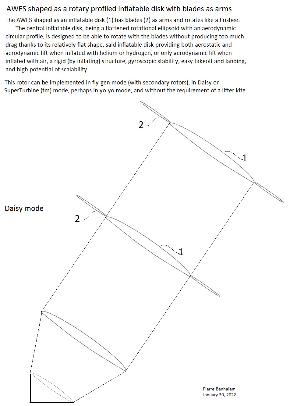
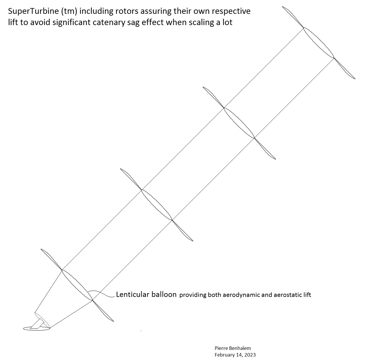
Another possibility is the implementation of rotors including their respective lenticular balloons in order to obtain aerodynamic and aerostatic lift in the middle of said rotors (where blade sweeping is lesser) and efficient (rigid) blades around.
The two sketches describe the same device. Then a video shows a minimal drag of the lenticular balloon despite the use of rudimentary equipment.
Yeah Pierre, on my radar screen for decades, and in all my notes going way, way back. Thanks for telling all the riff-raff, after our private conversations about it. And as I told you, there are many, many, ways to address and overcome what you’ve been consistently maintaining is an insoluble problem with SuperTurbine™: driveshaft sag, which as you now point out, does indeed have solutions, one of which is buoyant rotors, as disclosed in some forms by me from day one. After all that talk of yours about how SuperTurbine is limited to only a few meters, and now acknowledging one of the many reasons it is NOT limited to a few meters, I can only say this:
I’ve always been 30-40 years ahead of the rest of the world in AWE thinking, and there is NOTHING I’ve seen SO FAR, from ANYONE proposing ANY version of SuperTurbine™, whether it is rings of kites, rings of wings, tensegrity driveshafts, “carousels”, or anything you’ve seen from any other tinkerers, that was not already in my notes from over the years, and in my head from the days before anyone had ever HEARD of AWE. For me and SuperTurbine™, as a concept, there is nothing new under the sun, whether on-paper or or flying in the sky.
True, but the elements I disclose are mine, and were already disclosed on other topics . So I have changed my position in relation to our private exchanges. I have not divulged anything of your research that is not known. And as you say in your previous comment, you already knew all the implications.
Doug, I already mentioned the figure 88 as a possible solution. I am not sure you intended it to correct the drive-shaft sag (catenary effect), but at least it goes from a suitable intuition.
This topic is also about other torque transfer systems, although they are directly linked to SuperTurbine ™: it is not too difficult to find that this effect has been denied along the topic from after here.
It is also not too difficult to find that in the real world, actually no torque transfer device does not exceed a few meters in height for years of experimentation.
I am therefore pleased to have pointed out this problem and to have outlined a solution, including pointing to Figure 88 (which in my view presents the problem of a lower efficiency of inflatable blades).
Other solutions for autonomous rotor lift have been tested: Cyclic pitch control for Rotary Airborne Wind Energy Syst. using a rotation compensating slew plate .
All these solutions, including the one I am presenting, including also Figure 88 and similar figures, remain to be proven. This may be more difficult than expected: everything works well on paper but as you know, in the real world…
Just as people assumed Ockels was the originator of “laddermill”, it was already documented by me.
Like I said Pierre, what you’ve been saying about some mythical “insoluble” aspect of driveshaft sag was never correct, and nice that after all that talk, you finally looked a little more closely at my published drawings, which as you point out, had already handily disproved your recent thesis. Thinking of a pre-existing (here) variant was noted. Keyword (for me) “pre-existing”. Thanks for trying to help. ![]()
I did not see a rotor including a lenticular balloon in your drawings or elsewhere.
No. My message suite about the catenary issue starts on SuperTurbine (tm) and Serpentine, and other torque transfer systems - #28 by PierreB , in October 2022. And the possible solution I quoted (SuperTurbine (tm) and Serpentine, and other torque transfer systems - #52 by PierreB) is also in October 2022. So I had a complete enough view of this very serious issue and which has been either denied or ignored. And none of the solutions considered have been proven.
I would add that inflating numerous rotors with hydrogen or helium is not a trivial affair, and would lead to heavy maintenance, if it is a solution.
Because most of my work is not publicly disseminated, however I DID point you to a website of a pre-existing manufacturer of lenticular aerostat balloons I was in touch with 20 years ago for this exact reason, and you can see they are now celebrating their 30th anniversary.
I KNEW lenticular airships since 2010, by Pierre Balaskovic (Alysée) in Royan conference 2010.
See also my comments about lenticular balloons .
My idea is a rotor including a lenticular balloon, not the lenticular balloon as such. The goal is obtaining both aerodynamic and aerostatic lift in the middle of the rotor, while the rigid blades keep efficiency.