Using Durafly Excalibur for rotary takeoff in The Pyramid

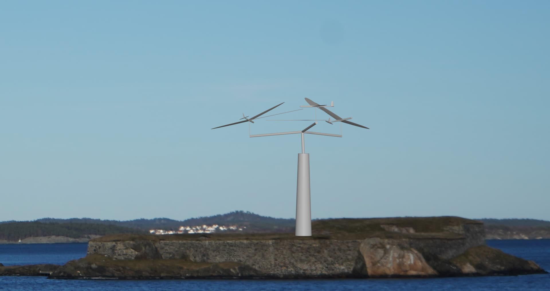
I am here considering using a Durafly Excalibur for testing rotary launch for “The Pyramid”. The launch looks something like this:

More info about the pyramid in this thread:

And the Excalibur looks like this:
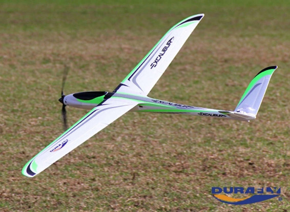
image

It has:

  • Wingspan b: 1.6 m
  • Chord c: approx 0.12 m
  • Weight m: approx 1.2 kg
  • Distance CG to tether attachment below fuselage d: approx 0.035 m
  • Wing area S: approx 0.19 m2

The triangular bridle between the three “plites” is assumed to have a radius R which will be 1.5x wingspan for now at 2.4 m.

Note this plane can me flown without the front prop.

Summary

The roll control of the Excalibur is feasible for the proposed launch sequence and you can choose to have inherent roll stability by selecting an initial roll angle for the “plite” according to the other system parameters. The design should scale without change in feasiblity.

Assumed roll torque authority

Lets assume the maximum C_{L, max} \approx 1.2. If we have set ailerons to provide max lift on one side and zero on the other, an approximate rolling moment would be

\tau_{\delta, max} = \frac{1}{2} \rho C_{L,max} v^2 \frac{1}{2} S \, \cdot \, \frac{1}{4} b

\tau_{\delta, max} = \frac{1}{16} \rho C_{L,max} v^2 S b

v is the kite flying speed, \rho = 1.225 is air density.

The specific value of moment per speed squared is

\frac{\tau_{\delta, max}}{v^2} = 0.027 \, \mathrm{Nm}

Rolling moment of the wing

So the kite is flying in circles in the plane of rotation with radius R. The inner half of the wing will experience lower airspeed than the outer half, so it will provide lesser lift and thus a rolling moment.

For simplicity we will assume the chord constant and the lift over the wind evenly distributed. This gives a good rough estimate of the moment involved. Later a CFD analysis or practical testing may give a more accurate estimate.

Also, the kite is flying at a roll angle to the plane of rotation which is \phi.

We disregard any effect of gravity and wind here.

The torque of the wing may be expressed as an integral

\tau_w = \int_{-b/2}^{b/2} \frac{1}{2} \rho \left(v \frac{\left(R + x \cos \phi \right)}{R} \right)^2 C_L c x \, \mathrm dx

\tau_w = \frac{\rho v^2 C_L c b^3 \cos \phi}{12 R}

The value of this moment per speed squared, at C_L = 0.6 and \phi = 0 is

\frac{\tau_w}{v^2} = 0.0125 \, \mathrm{Nm}

So for \phi = 0 the moment generated by the wing is much less than aileron control authority.

Tether moment of the wing

The tether moment is due to “centrifugal force” and at the same time the tether is attached (for practical purposes) at the bottom of the fuselage. This will create a moment

\tau_T = -m \frac{v^2}{R} \, \cdot \, d \cos \phi

The value of this moment per speed squared, at \phi = 0 is

\frac{\tau_T}{v^2} = -0.013 \, \mathrm{Nm}

This moment is also less than the supposed control authority of the ailerons, by a factor of approximately 2.

All moments

The sum of moments on the “plite” is

\tau = \tau_\delta + \tau_w + \tau_T

The range of \tau_\delta [aileron roll moment] is the largest of the three by far. The other two mostly cancel each other out in this configuration. We should be able to control the roll of the kite in this phase by feedback control on the ailerons.

But, both \tau_w and \tau_T both depend on \cos \phi, so \frac{\tau_w}{\tau_T} = const. For roll control to be stable without active control on the ailerons (\tau_\delta = const)), we require that

\frac{\partial \tau}{\partial \phi} < 0

This translates to (solving the derivative)

-\frac{\sin \phi \left(\rho C_L c b^3 - 12 m d\right)}{12 R} < 0

\sin \phi \left(\rho C_L c b^3 - 12 m d\right) > 0

This means that depending on the value inside the parenthesis, we can select a roll angle to ensure that the roll angle is stable without active control.

For this particular design we may choose any negative \phi, for example \phi = -30^\circ. We must use active aileron control to get to that roll angle, but after that, the “plite” should be stable in roll without any further adjustments to the ailerons.

An interesting observation is that we can impact the roll stability of the “plite” by adjusting the system parameters, most easily d, distance from CG to tether attachment point.

Edit: From this analysis it seems maybe we want the d to be rather large so that \phi is negative. This gives ut the benefit of wing lift pointing outwards, tightening the triangular bridle between the plites

Scaling

We will see what happens to a version of the demonstrator where all dimensions are scaled by a factor x. The mass is assumed to scale by x^3.

\tau_x = \frac{\rho v^2 C_L \left( x c\right) \left(x b \right)^3 \cos \phi}{12 \left(x R \right)} - \left(x^3 m \right) \frac{v^2}{\left(x R\right)} \left(x d \right) \cos \phi

\tau_x = x^3 \left( \frac{\rho v^2 C_L c b^3 \cos \phi}{12 R } - m \frac{v^2}{R} d \cos \phi \right)

The moment scales by x^3 but the ratio \frac{\tau_{w,x}}{\tau_{T,x}} does not change with scale. So we can conclude that at any scale, the launch scheme should still work fine.

3 Likes

I did a TRPTSim simulation of a configuration with this kite. The glide ratio of the kite is guessed to less than 1:20. Note such a configuration constitutes 3 kites.

julia> using TRPTSim
julia> excalibur = config(mass = 1.2
  , wing_area = 0.19
  , c_d_fun_coeffs = [0.025, 0.05]
  , design_c_l = 1.0
  , induction_model = :none
  , shaft_radius0 = 2.4
  , shaft_radius1 = 7.0
  , shaft_length = 20.0
  , shaft_diameter = 0.0012
  , aspect_ratio = 12.0)
julia> plot_power_curves(power_curve(excalibur, 1:0.1:15))

Power curve

plot

Details at 12 m/s wind

Details at 9 m/s wind

Other

We see rotary speed at 12 m/s wind is around 90 RPM. Power is 4 kW+. The moment that must be supported by the shaft and generator is around 450 Nm. The shaft tension is 400 N per “plite”; this is probably much more than the foam Excalibur can handle, so the kite must run at much less than that wind.

At 9 m/s wind speed the “plites” must withstand around 220 N each, which may be possible, though still probably optimistic. At this wind speed, the speed is 70 RPM, 2 kW power and 280 Nm moment.

2 Likes

Vacuum wrap those wings in carbon and you may be blowing more minds than mine. :exploding_head:
You know when you do something amazing and it raises more questions…
How much force will the aileron active control require? &
Is the triangle line between the “piltes” going to be actively wound? If not does launch require a 2.4m PTO set?
Is it going to be easy to transition from flying loops to gain altitude to wind blown autorotation at an elevation angle?
Still :exploding_head:

1 Like

I’m very impressed. Good luck!

If that is all you are doing maybe you don’t need the shaft for now, and so no need for a ground station and tower? You could connect the kites to the tether, or base, with a tetrahedral bridle and have a swivel somewhere.

Also, of course, in the beginning increasing the radius seems like it would make control much easier.

1 Like

The ailerons usually dont require too much force, but for sure if the wing is heavily loaded, the servos can’t cope. I believe you can get an estimate by assuming the force to area ratio of the ailerons match that of the whole wing then look at the geometry of the servo arm and hinges. The servo will have a rated torque. So I guess this is work to be done.

I was thinking the best start may be to have a single kite attached on a very short tether, then three kites, then three kites with triangular bridle and reel out. The expanding bridle requires more thought, but it would be nice if it could be solved manually (quick release maybe) or in a simplified manner. Anyways the expanding bridle could be postponed.

Also tilting from vertical to elevation angle. I think this is in the far future here. First fly a lot in zero wind and vertical, powered from the cartwheel. But I guess a manually operated pan/tilt base for the whole thing could be interesting. Once you start tilting though, there is quite a bit of software that must be written to keep it from falling. This is also far in the future :stuck_out_tongue:

The good thing about planning I guess os that you see how much work is involved

1 Like

I agree that starting simple then adding feature step by step would be a smart way to go about this.

I think you could extend the shaft (reel out) quite a lot with a smaller bridle, though probably not all the way. Flying with the short bridle is a very good first step though…

1 Like

Congratulations for the simulation @tallakt.

Please what would be the Λ value?
I got a little more than 0.053 by dividing the sum moment (450 Nm) by the sum tension (1200 N) and by the looping radius1 of the kites (7 m). Is it correct? I used from the pdf pages 6-7:

To go from an Λ value to the actual moment, multiply the Λ value by the looping radius of the kite and the shaft tension.

I also got a little more than 0.053 by using Tallak’s formula but by replacing radius0 (2.4) with 1: 1 divided by the square root of (tether length² − radius0² − radius1²).
If I use correctly (?) this formula, I get radius0 divided by the square root of (tether length² − radius0² − radius1²) = 2.4 times more, so about 0.129.

But if we were to extrapolate from the page 11 of the pdf, it seems that Λ value would be more or less the radius0 / the tether length, so 2.4 / 20 = 0.12, then about 0.129 by applying Tallak’s formula (see just above).

1 Like

This is where the theoretical studies in the report meet more realistic conditions in the simulator.

The kites are not producing around the loop equally as you see on the plots of C_L. Also there is rolling to provide a vertical force, which I see does not seem to match entirely what is necessary. So also some work is required to correct these details in the simulator.

For this short shaft, the simplified approximated \Lambda calculation is probably not too accurate.

I dont have access to my computer now so I will give more numbers about the chosen \Lambda value later. What I can say is that the shaft is short and stubby and the limitation I took into account was radius vs wingspan and tether drag, not moment carrying ability. Though for such a short shaft it should carry moment fine I suppose.

Also, my focus here was to see if the launch was feasible. So I did not focus too much on shaft dimensions. But I dont think there is a lot to choose from, due to the reasons above. I would say first get more accurate measurments
of lift and drag of the Excalibur before optimizing the shaft shape… Modifying the shaft shape would be changing the size of tether and bridle, so that could be done quite easily pretty late in such a project

2 Likes

If I’m not overlooking things one way to do that would be with the tetrahedral bridle I described. You’d unwind it through a ring in the center of your ground station and the three tethers connected to the central tether would give you an increasing radius until your outer triangle takes over. You’d have to deal with the slack outer triangle until then though, and after that with the extra drag from the tethers that are now slack.

After you’ve figured out vertical maybe go for elevation angle, or some higher elevation angle, gradually reducing the elevation angle, without the tilting. That’s the mode of flight you want to solve and there’s maybe less chance of breaking your kites if tether length is 30 centimeters. If a shaft length of 20 meters works I don’t see why a shaft length of 30 centimeters wouldn’t. What’s the need for a vertical take off?

Also if your ground wheel is powered and your shaft short you wouldn’t be dependent on wind for testing, and be subject to lulls and gusts. You could put it inside and run it for a few days.

Edit:

Actually, disregard that, if you’ve got the shaft you’ve already got your tetrahedral bridle and expanding bridle, so no slack lines. You’ve now got to worry about ground clearance if you’re not doing a vertical launch though.

The only way I now see for dynamic changing of outer bridle diameter is with a (highly) geared motor in each kite. That is more difficult but also not overly so I think.

1 Like

Now I understand what you were saying and it does seem like a good way to get past the initial testing phase. For a commercial system I would prefer to not have slack lines, but that is way far ahead…

I was always thinking the outer bridle diameter had to change and that is more difficult to make IMHO.

1 Like

I can now see a few ways to change bridle diameter. No comment on if they are good or obvious ideas or not. The easiest would be to put a motor with a high gear ratio (so that the motor can be weaker) in each kite that unwinds and winds up the tether connected to the previous or next kite.

Another way would be to determine your maximum diameter and make your triangle. Also determine your minimum diameter and put one stopper on each line for the minimum and maximum diameters to have the kite be able to move freely between those. Maybe that’s enough and the system self balances? You’d change diameters by flying the kites in a wider or narrower cone than 90 degrees. If that isn’t enough, you could add more stoppers along the tethers to act like static gears. You’d have a spring loaded cap in your kite that would be lifted up by the stopper, a sensor that sensed the position of the cap and activated a motor driven cam or something to keep the cap closed on the stopper after it came down again, or unlock it to be able to switch gears. You could also just clamp your tethers in the kite without the stops, or do something with friction, but maybe that results in uneven tethers lengths. Or do the above but now with a motor instead of with the tether angle.

With the configurations above you don’t need to worry so much about ground clearance and slack lines during take off I think. During take off and until you decide to change it you’d automatically have your minimum diameter.

2 Likes

Possible gearbox 100:1

Possible motor/generator

Not a suggested configuration, though may suggest price range for a suitable generator and gearbox.

I am using a \Lambda of 0.055 as calcualted by a heuristic function suggested_lambda(configuration) in TRPTSim.

Of course there is a lot of detail work left to do here. Eg; use zero \Lambda at low winds to be able to fly in less winds.

The shaft itself can tolerate a \Lambda of 0.13 before collapsing.

Also I see the system is not really sensitive to choice of \Lambda, as shown in this plot:

plot

Because lower \Lambda gives less torque but more forward speed, \Lambda must only be approximately controlled to get good power output. The “break” in the curves at high wind speed is due to depowering at high tension at tether safe maximum tension.

Because we are not too sensitive to selecting optimal \Lambda and we may go up to \Lambda = 0.13, In a real design we would probably opt to reduce tether diameter for better performance in lower wind speeds, then use a higher than optimal \Lambda at higher wind speeds. This way we could improve on the constant \Lambda power curve. The simulator does not yet allow for varying \Lambda by wind speed, so I have just plotted two curves for high and low \Lambda and a thinner tether than the one originally selected. The optimized windmill would have \Lambda = 0.040 for low winds speeds (green curve) and \Lambda = 0.095 for higher wind speeds (red curve).

plot

2 Likes

Crikey
Surely a smaller torque than this will suffice for the winch between the plites. Looks v heavy
Often thought that an electric fishing reel would be a useful AWES modelling tool

That was for the main shaft

Oops apologies.
I saw the torque number thinking it was a motor. Doh

1 Like