Laddermill

Hi Doug: when you look at the drawing, the wind comes from behind you.

That said I think that in all variants, the Laddermill is something like the other device we are discussing, Advanced Kite Networks. There is little chance that any of them will be built and work.

OK I understand now. A very conceptual sketch, might be missing a few critical details, like how a stack of blades hanging off one side of a vertical line would stay so-oriented, as just one example. Yes I guess it is possible a laddermill of the types we’ve been discussing never gets built. Talk is easy, building a bit more difficult. Hard to say anything will happen until it DOES happen, especially in the field of AWE! :slight_smile:

Orientation would be ensured by active control.

Still seems like the rope would twist as the blades were simply blown downwind.

Yes, unless the aerostat is quite huge, which by the way might not even be enough.

I could also provide another reply of type: this is a terawatt-scale system which will power the world; I need a lot of funding to make it; when AWE will be realized, this system will become obvious like Wright brothers’ invention became.

1 Like

The term “Spidermill” was used to designate the crosswind Laddermill version that is represented in the figure 4 of the pdf available on Comparison of concepts for high-altitude wind energy generation with ground based generator | TU Delft Repositories :

Title
Comparison of concepts for high-altitude wind energy generation with ground based generator

Author
Ockels, W.J.
Lansdorp, B.

Figure 4 Ockels Landorp

Wubbo Johannes Ockels :

Feb. 16, 2021, post by Dave Santos:
Wubbo’s LadderMill Patent, that JoeF links to here, is a good case-in-point. The basic LadderMill idea was overlooked public prior art by Doug Selsam, in the 1970s. It was not very workable. Ever the resourceful astronaut, Wubbo continued to work the problem, and turned away from the vanity of patents. His final AWES vision, of synchronously networked kites he called a “SpiderMill”, was fully open-source [AWEC2011]. Many other AWE academics have not yet made the transformative Open-AWE journey Wubbo accomplished before his untimely death

Yeah I knew it was time to bring in Dave Santos.
OK I looked at the document and the laddermill illustrated is ALMOST EXACTLY IDENTICAL to my original drawing.
The version where the wings also travel crosswind as independent kites tethered to the loop is a “nice try” but not compelling in terms of actual workability. If nobody can even build a regular laddermill, they are certainly not going to build a crosswind version as in that paper. That’s why they went to the fallback position of “kite-reeling” where they are now stuck. And I do not see the term “spidermill” used in that paper, nor do I see what similarity to a spider exists. Meanwhile it seems to me that every goofy new 2-second video stunt Santos comes up with mentions “spidermill” in some way, including his latest “Jalbert” excuse for his endless lack of progress. To me, this whole conversation, as usual, is just getting too stupid.

"Spider-Mill" Dynamics (Review and Update) :

“Spider-Mill” Dynamics (Review and Update)

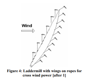
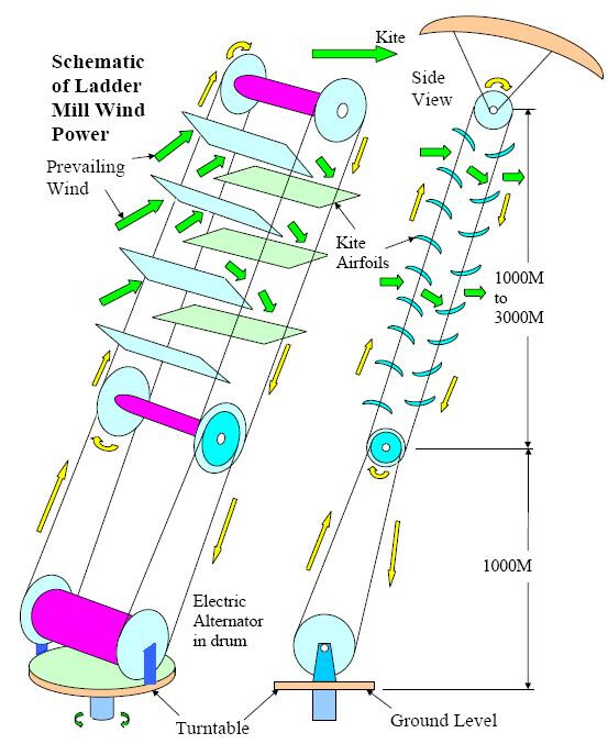
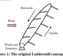
TU Delft (and Doug) early on recognized that a coordinated gang of kites was an essential AWE scaling method. Delft’s laddermill has morphed into a “Spider” concept that Wubbo Ockels introduced to us at AWEC2011. A “Spider-Mill” is rigged like an Inuit dog sled, whereby each kite along a common gangline is free to sweep or not, depending on the power pumping phase and windfield structure. Pairs of opposed kites orbiting a mainline were studied by Delft as a means to avoid much of the line drag of single sweeping kites.

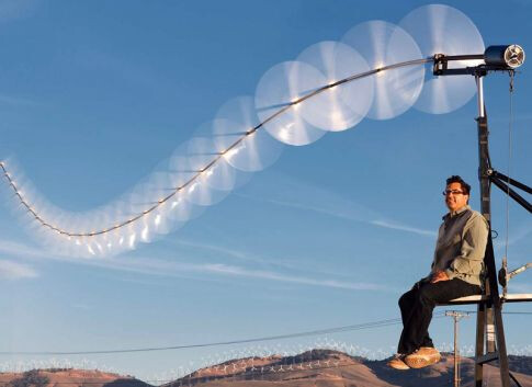
During this period i was learning hands-on about classic kite trains under various masters and was honored to help Terry McPherson fly a record 39 fighter kites from one line. These flights were existence proofs that a bunch of marginally stable kites fly well together, showing “aggregate stability”. Wubbo asked for the video link (below) to this sort of kite train and his reaction was “fabulous!”. Physicist and sci-fi god, Rudy Rucker, tweeted rapturously about the “sky seething with chaos”.

We see in these flight dynamics an amazing embodied computation whereby kites “in parallel” solve complex trajectories across chaotic turbulence in real time, for stable static force. To tap these kites as a pumping energy source minimally requires a simple control signal, much like the rowing coxswain’s “Stroke!” call, to coordinate the pumping of the gangline, and each kite needs a variable AoA servo input to power up or down, according to its place (phase) in the pumping rhythm (phase space).

For Spider-Mills, the common mishap is for a kite to collide with the tether or another kite. Opposed kiteplane pairs especially are challenging to perfect, owing to higher inherent potential for collisions and unrecoverable fouling. Staggered single kites on tri-swivels, as classic kite fliers rig, recover from temporary fouling and the danger of kites directly colliding is resolved.

With small trains collisions do no damage, and its practical to ruggedize contact points as the scale grows. At some point its worth avoiding contacts with active “chaotic control”. Unlike brute-force control, chaotic controllers work by nudging unstable elements away from failure states. When a kite wanders towards the gangline, a small correction is all that is needed to veer its orbit clear.

A tall spider mill does not necessarily power up and down all at once, but can send pulses of tug traveling down the gangline to the base. A staggered rig naturally supports helical power waves moving down the line. Each kite along the gangline acts in phase to the common clock signal.

The ultimate Spider-Mill may well be assembled and disassembled in mid-air by docking kiteplanes, but the paradoxical problems of large kite arrays laid out on the surface, prone to cascade-launch from any sub-unit, are spontaneous array launch risk and required “killability” (pending topics).

The old McPherson “spider” train video- Record Fighter Kites

CoolIP ~Dave Santos 12Oct2011 AWE4460


Comment and development of this topic will be occurring here.
All, send notes, drawings, and photographs!

Terms and aspects:

Related links:

Commentary is welcome:

  • v

I will recite the key points:

Dave Santos 12Oct2011

Delft’s laddermill has morphed into a “Spider” concept that Wubbo Ockels introduced to us at AWEC2011. A “Spider-Mill” is rigged like an Inuit dog sled, whereby each kite along a common gangline is free to sweep or not, depending on the power pumping phase and windfield structure. Pairs of opposed kites orbiting a mainline were studied by Delft as a means to avoid much of the line drag of single sweeping kites.

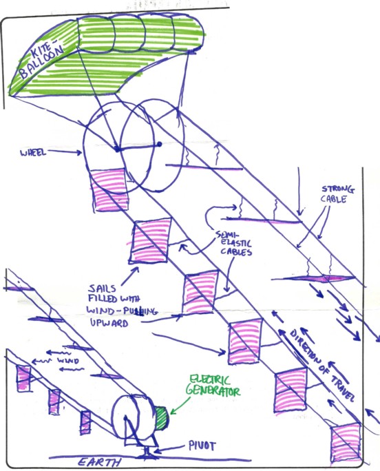
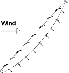
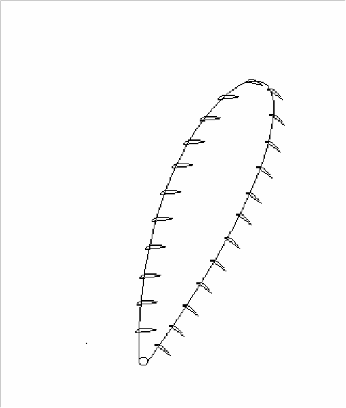
There is no doubt: what Dave Santos described in 2011 by using the term of “Spider-Mill” is consistent with what I have sketched (“pairs of opposed kites orbiting a mainline”), and with the single “swinging” wings" version of the Laddermill shown in figure 4 of the publication I just referenced, using the same term of “Spidermill” with another spelling, both being crosswind kite devices in Laddermill configuration.

It is clear that for Dave Santos the term “SpiderMill” had a quite another meaning in 2011 (“Pairs of opposed kites orbiting a mainline”) than currently: Subscale SpiderMill R&D Progress.

From a cross wind version (figure 4) of the Laddermill we go towards a sort of generic term denoting “higher-order AWES topologies somewhat reminiscent of spiderwebs”, using the same term of “SpiderMill”, while continuing to rely on Wubbo Ockels as the reference.

You can clearly see here what Dave Santos sees as the evolution of Spider Mill ideas is in fact a kite turbine (or superturbine tm (C))

It’s clear, he doesn’t want multi kites pulling in short tugs out of phase
He sees a progression to helical pulling
And common time is a continuum so continuous working kite power loops makes sense.

Yeah, good we agree

Once again, it was clear to me I was reading more melodramatic writing of Dave Santos, above. (sigh)
Meanwhile I am just going to resume the previous conversation about laddermill, lift and drag:

  1. There is not always a fine line between a lift and drag situation. This is where wind energy does entail a few subtleties. Even the Savonius rotor is said by advocates to enjoy “lift” during certain parts of its rotation, for example the rounded edge traveling upwind is said, by some, to create some lift in the manner of a typical cambered airfoil.

  2. Airfoils traveling at low speed are more likely to be in more of a drag mode than a lift mode, but as airfoil speeds increase beyond the ambient wind speed, even an airfoils with a downwind component to its direction of travel can be producing lift.

  3. The fact of nobody ever bothering to build a laddermill despite holding what amount to “laddermill festivals” and endless celebrations of the concept in Europe places us still in the early, stone-age era of even trying to get a single, primitive embodiment even running at all, which would be a far step from an optimized or perfected design. Obviously, for an AWE version, the first criteria over even power production would be if it could remain airborne, which is why the airfoils are arranged to help elevate the entire structure as much as possible, even when running slowly. It would be likely that early versions, probably running slower, might use more drag than lift, but with experience and continued development, more lift-based operation could be expected.

  4. Once higher-speed operation is accomplished, independent sideways (crosswind) travel would become less interesting since the airfoils would already be “sweeping” a good amount of area, and harnessing a healthy amount of power.

And as to whether John O. or anyone else should try to develop such a machine, the answer is yes, of course, the whole point is that someone should have tried it long ago, and it remains an untried concept, which is some pretty ripe, low-hanging fruit for anyone who wants to have a crack at an untried concept in AWE. :slight_smile:

Below are the documents of what was to be called “Laddermill”, from
http://www.speakerfactory.net/wind_old.htm :

From the drawing it seems that the bottom wings are deployed and pushed by the wind generating power by drag, while the top wings come down with an angle of attack leading to lift, which should rather make them go up, which would consequently cancel the rotation movement of the loop. Please some explains @dougselsam ?

1 Like

Hi Pierre: You are very good at archiving and providing images and past information sources.
This is getting a bit tedious, however, considering it is well-illustrated (thanks for providing the illustration) and explained in the past during the “Ockels” debacle.

First I would say this was a quick sketch, and probably the first drawing I ever made of this idea as a teenager. As such it is very basic and does not show finer points such as more curved paths for the moving cables with wings, and exact angles for these working surfaces. Surfaces would only be powered by drag at startup, and wherever their direction is downwind and their speed is lower than the prevailing wind speed, maybe at the bottom, traveling directly downwind, but even there, only at startup. Once running, the entire loop should be running faster than the windspeed. I believe the whole path would become more curved, and the upper kite with wheels might even become unnecessary. The most power would be near the top of travel on the downwind side, but as it nears the top of a curved path, it would even be traveling partly upwind, still producing power. After going “over the top”, the wings, being hinged, would naturally assume an angle of least resistance that would simply support their weight without much drag as they glide downward. At all points the wings would either fall into a passive position with reduced drag, or a position where they are producing lift, helping the loops to rotate.

1 Like

The Laddermill: work in progress

Submitted to: European Wind Energy Conference, London, 2004

Prof. dr. Wubbo J. Ockels

Bas Lansdorp,

Jeroen Breukels,

Gertjan Spierenburg

https://repository.tudelft.nl/islandora/object/uuid:bacf3e21-1cae-4722-93e2-55f15fdcd3ed/datastream/OBJ

Another sketch and description of LadderMill :

image
(No, mine was the original concept)
image


image

This drawing is essentially a Laddermill on top of a cable drive. The problem is that the cable speed in the drive is much too slow to be effective.

This look likes the device (not a Laddermill but rather stacked rotors with rope drive transmissions, drawing reproduced below) related on Ideas for scaling up AWES based on a tethered airborne rotor driving a rope drive - #57 by PierreB :

@dougselsam 's observation was:

I think its speed is more or less the tether speed of a yo-yo system, i.e. about 1/3 wind speed.