It is a project from Dave Santos (@kitefreak). The Advanced Kite Networks is a study related to Preprint on "Concept for the Giga-Wind Institute "Plan Humboldt" Chapter". The PDF is available.
Figures 5, 6 (kite network), 15, 16 (power takeoff PTO, something like Paynes patent US3987987 figure 5) could be investigated in first.
I have some questions: do you envisage the use of Reversible kite or pivoting kite for oscillating motions? Please can you sketch the steps of a kite network trajectory, including the tether motion through the generators? Then when the wind direction changes?
In my opinion a positive point would be a good density, thanks to relatively short tethers for a huge kite network, and also thanks to its topology, avoiding brush penalty by single tether single kite unities that are ready to tangle at the slightest opportunity. But I have no idea if or how that would work.
I suggest you made a working prototype then, “test, test, test”, according to the motto of Dr. Fort Felker.
1 Like
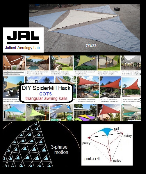
Ortho Kite Bunch has a similar spatial coverage. My account here does not allow me to post without approval, nor multiple images, links, and so on, so it will take months to catch up all the testing of the last two years. Meanwhile, the links provided give lots of details. Here is one more current experiment in preparation, using COTS tarps costing 100USD total-
For OrthoKiteBunch there is also a simplified version with two distant and alternating winches for an unity, and in yo-yo mode. That said superimposed kites would require a perfect control, leading to high risk of collision or tangle.
It looks that Advanced Kite Networks (AKN), settled within their multiple anchors could mitigate the management issue (no undesired brush effect), and improve the real potential density. With tests one would know better about AKN.
As an option I would envisage to simplify the architecture with a single kite area protected by a network of straps holding the tethers, and with holes (in the kite area) to let the air through for stability. An approximately circular in shape multi-anchored isotropic kite in Santos way could be deformed from the winches to change its aerodynamic design according to the forth and back trajectory, according to the wind direction, for example by towing on chosen winches. An automated simplified control system would be useful.
2 Likes
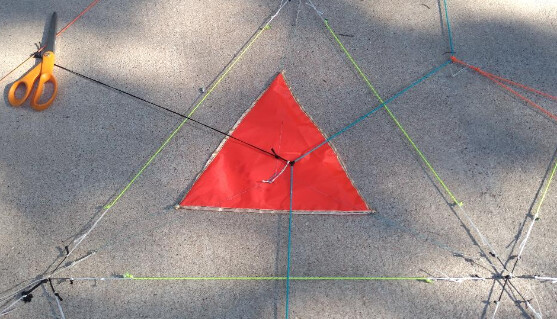
Here is the first unit-cell sail rigged in place this morning. It moves independently to tilt AoA in its cell. The overall spider also moves the same way, and a final lower stage moves the same way. It’s like how one can curl a finger, an arm, and torso independently at three fractal control scales. This makes the AWES able to do all-modes across all conditions, from calm to storm.
1 Like
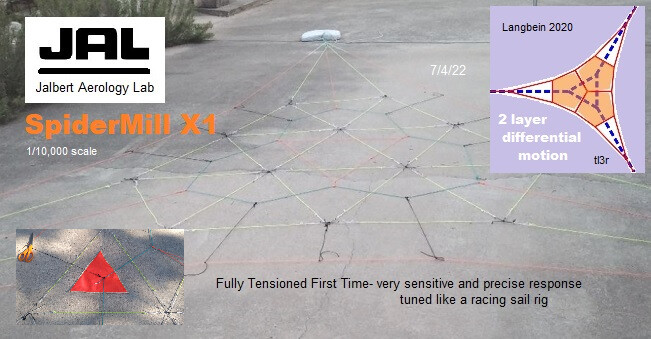
Here is the overall subscale SpiderMill two days ago.
Am only allowed one image and link per post, under Moderation restrictions, so my posting limit is gone fast. If I do not reply, it’s because of my posting ration or Moderators refuse or delay approval.
I fully agree about the second sentence. I would add that a very long tether for a relatively small kite is not a harmonious system. The first sentence is well illustrated by the Advanced Kite Networks. Now testing it and putting generator(s).
1 Like
Adding generators is being done by a separate team under Dr. Rutman (JAL co-founder) using VESC motor-regen components. “Solved…conceptually” means JAL team is confident the experimental validation will work.
Here is another conceptual source-
Assessment of an Alternative Concept for a
High-Altitude Wind-Power Generator
Max Langbein, Maja Ruby, Nicolas Gauger
pdf (iop.org)
From the paper-
"It has been shown that:
3r is comparable in terms of power output.
3r makes it possible to have a kite with constant angle of attack.
3r makes it possible to land and start the kites without additional equipment.
3r makes it possible to keep the kite airborne when no wind is present.
A key feature of 3r could be a constant power production which could be achieved by steering
the distance motor-generator accordingly while keeping a closed trajectory."
1 Like
In the Unit-cell picture …
Are you constructing the net upside-down before flipping over?
I admit to being confused as to how this design is intended to fly and operate.
I guess as per - - you’re making a big flying network of multiple Kixels (kite pixels) and letting out more line close to the wind to inflate the whole net structure. But in this network you also intend to steer each kixel.
So that cell (red triangle patch (kixel)) looks like it could be in the yellow line cell below the X1 in the second picture… Will all of the yellow triangle cells get a triangle patch?
I also admit to often being confused by the terms you use for your art. e.g. …
Spider the name for the whole kite thingey which stands up like a spider (on 3 legs) or something else that moves over the web?
Yes, the SpiderMill is being assembled upside down, as the unit-sail lines are rigged belly-up. For this initial version, the unit-sails move both passively, individually, like KiteLab’s famous 2009 3r paper-plate demo, and actively by shifting the bulk layers. It’s a learning curve.
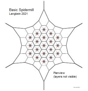
The term “SpiderMill” was coined by Wubbo at AWEC2011 to generally denote higher order topologies than single-anchor single-line. Some indeed look more or less like a radially symmetric orb-spider web, with any number of legs, 3 or more.
There are a lot of prior SpiderMill diagrams and testing records in the last year, covering the working details. A lot of relevant messages went directly to your mailbox, since the Forum here had my account blocked. Check your Trash Folder.
The Provisional Patent preprint has a glossary of new terms-of-art.
We had help from above-

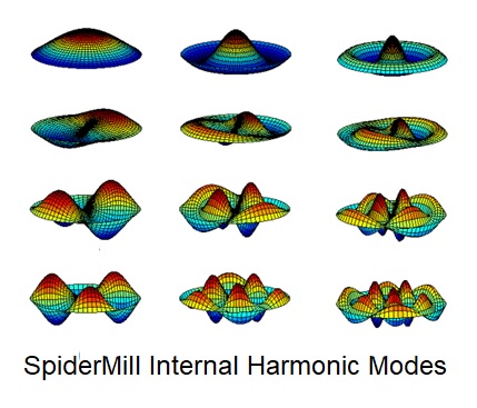
Theoretic megascale SpiderMills are studied to be tapped various ways, from bulk motion to local motion. Local motion PTO versions are predicted to favor these fundamental disc harmonic modes in matching load-demand to wind velocity-
Show your work, as a math teacher would say.
It’s a heuristic conjecture.
It seems more imagined than studied if it is “theoretic”
And by theoretic, could you maybe mean postulated?
I don’t think any of us can be authoritative about this yet
The theoretic basis here is dynamic similarity of conjectured SpiderMill harmonics to standard disc harmonics (applied to drums, for example). It does indeed require imagination to postulate boldly about AWE.
“Imagination is more important than knowledge” Einstein
1 Like
The fundamental of the Advanced Kite Networks is well described in the pdf linked in the initial post. I suppose Dave might prefer to explain some of the details in another context. So possibly the discussion could continue at https://www.researchgate.net/publication/361551510_Advanced_Kite_Networks.
1 Like
2 posts were merged into an existing topic: Slow Chat
This topic is about Advanced Kite Networks, everything about it, and nothing else.
Try to see if this method can work, the advantages and disadvantages. Considerations about AWEurope, AWE competitive fly-off, Wright brothers and so on, have nothing to do with the topic.
My question, based on the pdf, is the lack of description of how the power take-off (PTO) is achieved, especially with regard to wind changes. Can such a large assembly really work by crosswind flight in all wind directions, and in which configurations, or be a huge choking rag on its pulleys?
Also there is likely overloads: for example we can understand what is the power kite network as described on the Fig. 6, but what do the triangular elements have to do with it, and can they really fly crosswind?
I think a more focused and detailed description of the main envisaged embodiment could help.
2 posts were merged into an existing topic: Slow Chat
Hello Pierre: One thing I’ve been meaning to address is the choice of words “ADVANCED Kite Networks” Applying the word “advanced” to what is already a nebulous category “kite networks” seems to me as an attempt at self-flattery, by inserting a complementary word into an attempted introduction of a new terminology for ones own version of what we’ve all been talking about for over a decade.
If people want to refer to a telephone system as a “network”, that is understandable, because a lot of work goes into what is basically a 2-dimensional criss-cross of phone lines across the landscape (like a net).
I have seen AWE references to multi-kite, multi-blade, and multi-rotor systems, as “network”. Not so sure a single line of something is really a “network” - where is anything resembling a “net”?
But to call any of them “advanced”, without showing WHY it is “advanced” seems like putting the cart ahead of the horse.
Instead of “advanced” how about “highly-effective”? Could we rightly call a diagram, or a few slices of cloth laying on the ground, “highly effective”? Probably not unless we knew what result they were “highly effective” at attaining. In the same sense, why would we say some proposed configuration is “advanced”, ahead of any fact or evidence of such advancement. What has a mere diagram, or a few pieces of cloth, done to deserve any of these titles? Or does “advanced” refer to some crackpot verbally “advancing” the mere idea that it is good (highly-effective) for something?
2 Likes
The opposite of “advanced” is “retarded”.
So if a given configuration is at first, tentatively called an “advanced kite network”, then, if anyone actually builds one and tries to run it (unlikely) and it turns out that it does basically nothing, would the promoters then be willing to switch the name to a “retarded kite network”?