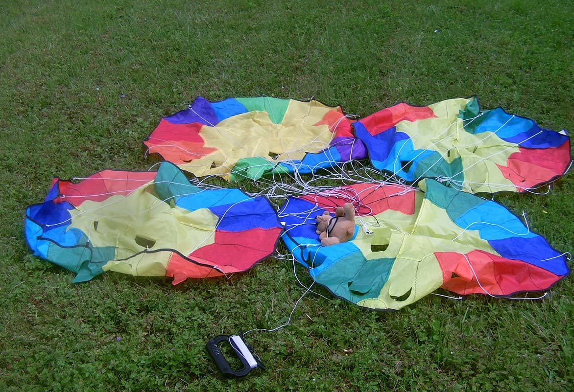
In the sketched arrangement, the Rogallo parachute kites will have difficulty deploying, being in each other’s way. This was demonstrated by testing four small parachutes attached to each other as shown in the photo, opening and inflating at the same time for only a fraction of a second due to the interaction of kite traction.
So Airborne Wind Energy System based on steerable Rogallo rescue parachute is updated.
The turn radius can be a significant element in order to optimize the power to space use ratio.
The turn radius (or the radius of a turn) is the horizontal distance required for an aircraft to turn. It varies according to the bank angle and the square of the true airspeed.
To extrapolate by simplifying, the heavier a kite is for the same wing loading, the faster it must fly to ensure its lift and maximize its performance.
As an example, a very efficient rigid wing with a high wing loading will fly quickly so as not to fall and maximize its efficiency. As a result, its turn radius will increase considerably (to the square of the airspeed). So the power to kite area ratio will be maximized, unlike the power to space use ratio.
1 Like
The work around of course being to tie kites together.
This reduces their turn radius and keeps speed high
In reality, these land and space use diagrams take into account the normal operating parameters of AWES, but only within a narrow range.
A cable break on an AWES could propel it far beyond these normal limits, with the entire AWES and its cable trailing for tens of kilometers and potentially causing considerable damage of all kinds.
The safety zone would extend well beyond the land and space use zone where secondary activities could be considered, unless the tethers are completely secure.
The multi-tethered and multi-anchored AWES would not remove this issue. Indeed, when one tether breaks, the other tethers tend to follow and break as well.
Perhaps Drone or kytoon for some uses? could have a function of detaching the tethers at the level of the respective AWES, or even destroying soft kite-based AWES with a blade.
In any case, it would be appropriate to distinguish between land and space use under normal conditions, and the security zone which has no defined limit, the two constituting major and distinct problems, whatever the AWES used.
Perhaps a depower tether retaining the AWES would be a possibility, a bit like the circus tent in the video which is still retained.
Yes, all the tethers in the basis on the circus tent broke, while said circus tent was retained only by its summit in “depower” position.
A conclusion: multi-tethered multi-anchored AWES are a dead end concerning safety improvement.
Another conclusion: said circus tent on the video could be a model to depower the AWES when the tethers break.
Wow, Pierre:
We have a similar tent recently installed for selling Christmas trees here in one of the windiest parts of the high desert, which is also subject to regular, strong dust-devils that put dirt in the teeth of hang-gliders riding them as thermals over a mile high in the air! I was outside one of my homes in a nearby neighborhood one afternoon when it had just started to rain, and some combination of a dust-devil and weather-borne tornado suddenly started shaking my big, solid, plastic fence. I could only try to stabilize the fence as I watched a big tree across the street snapped off like a twig at its base - leaving shards of splintered wood in every direction - this was maybe just 100 feet away from me. I’ll have to keep an eye on these tents - they must be vulnerable, especially to dust devils! ![]()
Power to space use ratio for AWES could have been named power density, or simply density (MW / km² for land use, MW / km³ for space use with AWES), as is done for traditional tower wind turbines.
Data investigation of installed and output power densities of onshore and offshore wind turbines worldwide - ScienceDirect
In the introduction:
Systematic quantification of the installed power density is important because current estimates of it over land vary by a factor of 9.1, from 1.5 to 13.6 MW/km2, with a mean of 7.2 MW/km2 (Fig. 1), due to different definitions of the land area that constitutes a wind farm.
Secondary uses, such as agriculture or fishing, are easy and risk-free. Therefore, the spaces between wind turbines can be neglected when studying land or sea use, except for the fact that they impose a discontinuity.
The situation is different for AWES farms and is complicated by the length of the high traction tethers and the mobility of kite systems which depend on the direction of the wind which also enlarges the area of operation, making agriculture or fishing risky, not to mention the risk that a gust will carry everything away, the AWES dragging for kilometers.
For a single unity, the power density would be defined by the ground station (minimal footprint), plus the length of the tether as the radius of the exploitation area (gigantic footprint due to safety issues).
For an AWES farm, ground stations are extended by the length of their respective tethers, these lengths being maximum upwind (flying over the zone with ground stations) and less downwind (flying over an additional area), the AWES covering a frontal airspace shared between the units.
In addition, the yo-yo mode is limited to 4/27 for the power available in the wind. Furthermore, the reel-in recovery phase divides this limit by approximately 2, being optimistic (see Mutiny tests).
Well. it’s not. If one can fly one parachute (or parakite) on a single line there is no principled obstacle on chaining dozens of them as Doug’s serpent but with parachutes instead of propellers - so pull could be increased several times for the same wind front width.
Sure, you cheat Bets by having a long and narrow compound parachute, but who cares? that was the point of using kites so they can go much higher.
And the 4/27 assumes a drag coefficient of 1 which is incorrect from the beginning. If a dozen parachute train increase drag more than 4 times, then voila’ Betz limit is surpassed without increasing land use.
And the closing/opening operation at end strokes is faster with smaller parachute(s)
Given the content just above, it seems more than necessary to reiterate some basic points, with some interpretations.
The Betz limit is 16/27. It applies in particular to wind turbines.
This is discussed on Betz limit and power available in the wind based on
The Betz limit applied to Airborne Wind Energy - ScienceDirect.
Highlights
•
AWE drag power systems can harvest up to 16/27 of the power available in the wind.
•
AWE lift power systems can harvest up to 4/27 of the power available in the wind.
In the abstract:
Another contribution is to show that Loyd’s lift power AWE devices during the reel-out phase can harvest up to 4/27 of usable power available in the wind, i.e. exactly 1/4 of the theoretical limit of the horizontal-axis turbines and AWE drag power systems with ideal airfoils.
So, AWE drag power systems [I would prefer rotary, and fly-gen (stationary or crosswind) systems, but it is another story] could reach the Betz limit, in theory.
Things are different for yo-yo (lift) reeling systems where the swept area is going downwind (is dragging) during reel-out power phase, at an idealized speed which is 1/3 wind speed. The power available in the wind is 4/27. And this is perfectly demonstrated in the publication in question. This can be easily verified by multiplying the force by reel-out speed, as shown here.
Note: as I repeat, a drag-based parachute or a parasail (with drag and lift) can cover the area swept by the “ideal airfoils” (which use lift during crosswind flight) with the same 4/27.
The parachute or rotor trains of SuperTurbine on a line capture a wind zone corresponding to that captured by all the units (before aerodynamic loss calculations): this does not affect the Betz limit in any way.
That covers the basic elements.
Now, on the specific case of a parachute with a drag coefficient Cd greater than 1 or 2 or a parasail with a drag coefficient Cd of 2.727 (and therefore a reel-out force greater than that of “ideal airfoils”), the 4/27 could be exceeded according to a simplistic and probably incomplete view I suggested. But that does not happen, at least because the Cd tends to decrease as the Reynolds number increases. See the values for a parasail. See also the low Cd of the gigantic Chinese 5000 m² parachute.
After all, one could design rigid kites or super-efficient blades that would also exceed the Betz limit (the real one, the 16/27 one): but this does not happen, because the Betz limit takes into account the open-disk actuator area. And it should be the same for the 4/27 in reel-out phase, regardless of the drag coefficient (if the Cd is higher than 1, the referenced area also increases, then including the parachute and its surroundings which increase).
I can not read that paper only the abstract, so I cannot confirm or deny what it states without reading a convincing demonstration.
As for the first message in this forum’s topic - As I said, the formula that “confirms” the paper is:
Assumes a drag coefficient of 1. Tests on parachutes exhibit coefficients up to 1.7, while autogyro rotor data I linked somewhere else are 2.0 which already indicate a 8/27 power potential. And since an autogyro rotor in parachute mode is showing a counter example of an actual lift-based pumping system which contradicts the paper claiming a theoretical 4/27 limit I see no reason to take an abstract of a paywalled paper as a proof because it is proven wrong.
It doesn’t matter.
On a publication I know, and according to a specified Reynolds number. Other publications that I have cited give other values.
Please read all the links and comments I provide on this issue before making an opinion.
The 4/27 limit for yo-yo mode is logic: the swept area goes downwind, the apparent wind speed being 2/3 real wind speed. The paper proves it. My demonstration ( I put again below) proves it, using the formula of force multiplied by reel-out speed to match the formula of power at Betz limit. This has nothing to do with the drag coefficient. This is related to the loss of apparent wind speed, given that the swept area is moving downwind.
That said when the Cd increases beyond 1, we can reasonably assume that the area swept increases also (see my previous comment), being the parachute (or autogyro) area plus the area of air deflected by the parachute and which increases if the Cd increases.
Thus, the demonstration remains valid even if I use a Cd of 2 (the disk area becoming 200 m² by taking account of additional air deflection), which I do below, with a temporary conclusion.
Note: 4/9 is (2/3)². It is because the traction force goes with squared wind speed.
Now, with a Cd of 2: the traction force is 12000 N instead of 6000 N. The result is: 40000 x 4/9 = 17776 W, so exactly (to within decimal places) 1/4 of 71104 W, by taking account of the doubled swept area, which becomes 200 m² due to the additional deflection of air around the parachute or autogyro.
In practice this would mean that the higher the Cd is beyond 1 or even 2 (a value much higher than that from tests on a parasail that was not a scale model linked here), the more the units should be spaced out to maintain their aerodynamic efficiency.
I disagree, the swept area is considered according to the swept rotor area. For axial HAWTs is Pixradius squared, or height x width for VAWTs.
Betz isn’t computed for swept area PLUS or MINUS some imaginary ring surrounding the rotor’s swept area depending on whether the thrust force coefficient is greater or smaller than 1.
EDIT: units need to be spaced out even for ideal Betz turbine because it assumes a final (down wind) drop in velocity to 1/3 of the undisturbed wind speed. So that volume of air needs a cross section larger than the propeller’s swept area anyway
It’s not a question of agreeing or disagreeing. The 4/27 ratio for the yo-yo mode (which doesn’t work like a rotor for a HAWT but relies on the pulling force exerted by the tether) is scientifically established and mathematically proven (see the references in my comments above). Everything else follows naturally from this scientific truth. There’s nothing to argue about. I don’t see the point in continuing this discussion and I prefer to end it.
The Science Direct page you say I should consider is only a snippet lacking any demonstration and asks me to pay for the full PDF. Unless you can show that PDF a proof one cannot see doesn’t count as proof.
https://www.sciencedirect.com/science/article/abs/pii/S0960148118304427
The_Betz_limit_applied_to_Airborne_Wind_Energy.pdf (1.3 MB)
The paper. I haven’t read it.
Some weird claims made by Pierre are that a kite is dragged kilometers in case of tether break (I haven’t seen examples of that happening, and if it does, don’t use kites that do that), that AWES need to be spaced double their tether length apart (you program them so that they avoid each other), and that land below the tethers can’t be used for other purposes (you tell them to avoid the area or land when human or animal life is detected, while reliability is still low).
Since AWES fly crosswind, only having the fast moving blade, equivalent to the outer 20% of a wind turbine blade, it stands to reason you would have much less of a wake and the systems can be placed closer together because of that.
Thanks - it’s simply wrong. Lots of assumptions including the one that if the Betz model assumes a maximum disc area thrust coefficient Ct of 1 for a turbine extracting power from wind passing through it then all and every rotor exposed to wind can not possibly experience a higher thrust than in the Betz model. Then make speculations about hybrid energy harvesting from a wind turbine moving down wind using both propeller spinning to extract power and line pulling which are… useless and wrong about what happens at the limit in which the rotational harvesting is zero.
If that theory would be correct it won’t allow a drag coefficient of a descending autogyro rotor (same as thrust coefficient in a HAWT) significantly greater than 1. Which isn’t the case.
I guess the wake effect can be more directly assigned to the momentum transfer to the wind front by the thrust force. But the fact the kite also gains altitude as it reels out, the wake is spread vertically because the kite circles (or loops) move higher as it pulls line. A HAWT that gradually moves up and down several rotor diameters would also have a much less powerful wake.
Edit: also interesting fact - a Cd of 2.0 - autogyro again in “lift mode” - when applied to the 2/3 apparent wind speed, it translates to a Cd of 0.8888 applied to the full wind speed.
2.0 / (2/3)**2 = 0.8888
Funnily when Betz maximum of 16/27 Cp is reached, the Ct coefficient gets exactly 0.8888 too.
Also the actual speed passing through the rotor at Betz maximum is 2/3 of undisturbed wind speed, and if applied to that speed the Ct of 0,8888 of the ideal wind turbine becomes 2.0 (!!!).
The only relevant thing I saw in the last three comments (and other comments of the same ilk) is the content of the document under discussion intitled The Betz limit applied to Airborne Wind Energy and which is fully available thanks to the link provided by Windy here.
Since I cannot quote this document, I can nevertheless mention the pages 17 (“this is related to the loss of apparent wind speed” I mentioned before having quickly read the document and the relevant passage) and 20 which shed light on the 4/27 limit reached in yo-yo mode. See also the figure 7.
I would repeat that this limit should be divided due to the reel-in recovery phase and also the additional space used during the complete cycle, which reduces further the Power to space use ratio.
I have some advice to give for sleeping with the idea that AWE is better for everything: ignore the land and space use problems posed by long high-traction tethers flying in all wind directions; ignore this damn document that has the audacity to prove this 4/27 limit; ignore that for years of statements claiming AWE superiority, we only see HAWT, and no AWES, leading to ignore that AWE is becoming a fiction.
I don’t know who you are addressing this to, I haven’t made any superiority claims regarding AWES you list here. I agree there are several problems which can be discussed, all I said the theoretical 4/27 limit isn’t one of them since there is possible for a device to extract 8/27 during tether pull phase in pumping mode. I wasn’t ignoring that document, I simply said that if an autogyro can reach a Cd greater than 1 during vertical descent, that 4/27 figure is obviously flawed.
Since the document entitled The Betz limit applied to Airborne Wind Energy was also discussed on the current topic (here Power to space use ratio), I report my comment from the initial topic.