A major problem with multiple coaxial turbines (Superturbine, Daisy etc.) is that the higher the elevation angle, the greater the cosine cubed losses. At 45 deg. The correction factor is 0.354 and for 60 deg. the factor is 0.125! It is therefore essential to find methods to reorient the turbines to face the wind if we want to capitalize on the higher winds at altitude. I suggest three methods to do this, all of which can be converted to cable drive to avoid airborne generators and conductive tethers. I would appreciate your comments on the three methods and perhaps you can suggest others.
COSINE.pdf (70.2 KB)
PULLEYS ORIENTATION.pdf (63.4 KB)
UJOINTS SUPPORT FRAME.pdf (66.3 KB)
2 Likes
I think the problem you are presenting is relevant and your proposed solutions serve as a good starting point for discussion.
I would say not rely so much on mecanics to orient the blades, rather focus on blade orientation for blades that are tethered to the shaft rather than fixed. I dont have any concrete proposals though.
The other thing I am wondering: Why is the lifter better suited for pulling upwards compared to using the blades themselves? When the blades are pointing along the shaft (lift parallell to shaft) only a minimal lifter kite is necessary. And if the blades are tilted slightly upwards, you may even do without the lifter.
The reason I am saying this is that the lifter is motionless, so it can not easily handle large changes in wind speed. If the lifter is huge, it will place very strict requirements on the rest of the system to handle any maximum force.
The other way to solve this is to elongate the tethers. To me that seems to hold more potential than pointing the kite at an elevation angle larger than 60 degrees.
There is also an other thing that we discussed earlier (I dont have the exact thread ready); if the blades are pointing the lift slightly outwards, the wind gradient might be able to make the rig provide more positive lift at the top of the rotating sections compared to the bottom part.
1 Like
Please could you also point to where you found cosine cubed. To me the numbers seem very low…
The cosine cubed factor (see the simplified formula in the end of the paper, page 1532) concerns all AWES. For example a crosswind kite flying by an average elevation angle of 30° will have a cosine cubed factor of 0.65. You rightly point “that the higher the elevation angle, the greater the cosine cubed losses”, leading to the low (and correct) values you mention.
The problem is that AWES face two opposite requirements: flying, and generating. For the last a low elevation angle is required, but for flying it can be the reverse. As a result an AWES is a compromise between these requirements.
The solutions you propose lead to a likely optimal generation efficiency, but the lifting kite would make the full flying and lifting job, unlike the original devices that also provide some lift.
Moreover these solutions, and particularly the added frame and the bevel gears (superturbine variant) or universal joints, add cost and weight.
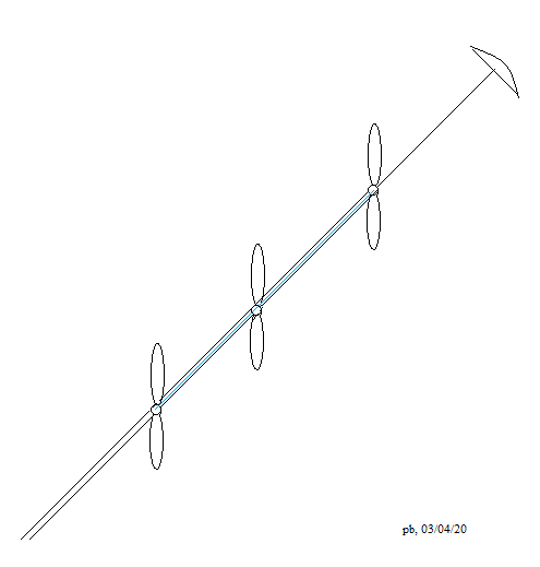
Another possibility sketched on Towards a crosswind version of Kiwee? is connecting the angle pulleys (to adjust the angle as for Kiwee) close to the hubs of the respective propellers with a rope drive then to the ground with another rope drive in continuation. The frame is only a bar connecting the propellers. Note that such a device can also be tilted in order to provide some lift, but with losing efficiency by cosine cube.
1 Like
I feel that it is much easier to increase the size of the lifter kite to provide more lift than to operate a turbine at a suboptimal angle. We require large amounts of lift to operate the cable drive. In order to generate significant amounts of energy we require a large lifter kite which must be automatically controlled, launched and landed. Increasing the size of the kite will not increase the cost much.
With multiturbine devices which we are discussing the only way to generate crosswind action is to traverse the wind window with the lifter kite. Since this kite will be controlled by a kite steering unit or auxiliary tethers, increasing the kite size will not appreciably affect the crosswind action. This crosswind action can be stopped in conditions of high wind to prevent damage to the turbines. If the wind is still too strong, and the maximum force is approached, then the kite system must be landed.
Gordon are you suggesting you would sweep your lifter side to side (or loop it) in order to sweep the stack of turbines (like a windscreen wiper blade…) across the wind window to increase their inflow speed?
A turbine blade may be rotary but being aligned axially to the wind direction means all of it’s motion is therefore in the crosswind plane.
No Kite System other than maybe a rail running, boat pulling or widely anchored set actually goes crosswind. The term crosswind is hideously misused in AWES science.
Now that you precised it, this seems to make sense. After all I did mention a link to a crosswind version of Kiwee on my previous post, the device being also a groundgen multi-rotor.
A lifter kite in normal sizes may be cheap and handles easily by a person. If you want to go huge, then the question is a bit different. Handling og a huge lifter may require specialized ground handling gear. Smaller turbine blades may be easier to handle in such circumstances. A small blade moving fst crosswind may do more for your net energy output than your huge lifter.
In the end, core values are such to generate a maximum power output with the fewest resources. Relevant resources in this context would be kite surface area, ground safety area, ability to cope with the minmax problem (a kite will generate very low and very high forces/power interchangeably) etc.
High glide number wings will eventually give you more energy per invested resources, as a rule of thumb.
1 Like
Moving the lifter kite across the wind window (crosswind?) will result in two advantages. Firstly the tether tension increases which ensures good performance of the cable drive. Secondly it will cause the train of turbines to move across the wind window, effectively increasing the apparent wind speed. This will increase the power output of the turbines especially if they are oriented to face the ‘effective’ wind direction. (To keep on topic.)
1 Like
A s a preliminary remark for this topic an evaluation of the aeroelasticity effects of a multi-rotor structure compared to a single larger rotor of equivalent power would make it possible to sketch the most appropriate solution in crosswind flight mode. Account should also be taken of the pendulum effect with regard to the wear of the material, including the tethers, as well as the interaction of these effects. Then these issues could be better evaluated according to the turbine orientation.
Positive…
Yes, sweeping or looping a lifter increases line tension by increasing apparent wind.
Negative …
Aerobatics requires extra line length for safe working. This has drag and mass implications.
Positive…
The extra tension can be significantly beneficial for tension transmission (like yo-yo).
The higher apparent wind will be beneficial for high up line mounted inline turbines (Kitewinder Kiwee) or kite mounted turbines (like Makani)
Negative
Sweeping and looping from above will add cyclic loading to components and cause irregular output.
As an aside, I’m quite keen to use a longer line and looping (tight) lifter above larger Daisy types.
Check my numbers. If we change the orientation angle from 30 deg to 0 deg then the increase in output power will be: 1/cos cubed (30)=1.54. If we assume the average wind increases by 20% at altitude, then the power will increase by 1.2 cubed = 1.72. The power will therefore increase by about 1.54X1.72=2.66. With an increase in performance like this, perhaps we do not need cross-window action. The increased performance will more than compensate for the extra weight and complication of u-joints, rigid frames or pulleys.
A major problem with multiple coaxial turbines (Superturbine, Daisy etc.) is that the higher the elevation angle, the greater the cosine cubed losses. At 45 deg. The correction factor is 0.354 and for 60 deg. the factor is 0.125! It is therefore essential to find methods to reorient the turbines to face the wind if we want to capitalize on the higher winds at altitude. I suggest three methods to do this, all of which can be converted to cable drive to avoid airborne generators and conductive tethers. I would appreciate your comments on the three methods and perhaps you can suggest others.
I feel that it is much easier to increase the size of the lifter kite to provide more lift than to operate a turbine at a suboptimal angle. We require large amounts of lift to operate the cable drive. In order to generate significant amounts of energy we require a large lifter kite which must be automatically controlled, launched and landed. Increasing the size of the kite will not increase the cost much.
With multiturbine devices which we are discussing the only way to generate crosswind action is to traverse the wind window with the lifter kite. Since this kite will be controlled by a kite steering unit or auxiliary tethers, increasing the kite size will not appreciably affect the crosswind action. This crosswind action can be stopped in conditions of high wind to prevent damage to the turbines. If the wind is still too strong, and the maximum force is approached, then the kite system must be landed.
Moving the lifter kite across the wind window (crosswind?) will result in two advantages. Firstly the tether tension increases which ensures good performance of the cable drive. Secondly it will cause the train of turbines to move across the wind window, effectively increasing the apparent wind speed. This will increase the power output of the turbines especially if they are oriented to face the ‘effective’ wind direction. (To keep on topic.)
Check my numbers. If we change the orientation angle from 30 deg to 0 deg then the increase in output power will be: 1/cos cubed (30)=1.54. If we assume the average wind increases by 20% at altitude, then the power will increase by 1.2 cubed = 1.72. The power will therefore increase by about 1.54X1.72=2.66. With an increase in performance like this, perhaps we do not need cross-window action. The increased performance will more than compensate for the extra weight and complication of u-joints, rigid frames or pulleys.
Pierre,
I fail to see how the Kitewinder system can be adapted to multiple oriented turbines. Auxiliary cable drives would have to be rigidly connected together with some sort of frame. This is like the pulley system I propose.
But as the connection would be made by the angle pulleys rather by the hubs, some significant adjustments would be required. I think a preliminary work would be building the different variants (pulleys, bevel gears, universal joints, angle pulleys like for Kiwee, and so on) of multi-rotor facing the wind or the apparent wind.
An example of connection by the hubs is given below. Unfortunately the apparent wind would be different according to the side of the turbine.
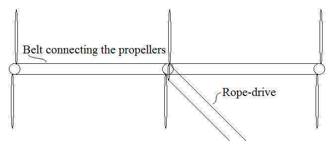
The frame would be a bar like this, the turbine being correctly oriented:
And as the rope-drive transmission avoids the weight of the generator in flight while the system scales up, a single larger rotor would be simpler.
I like your idea of using bars to connect the oriented turbines. The problem is to connect the cable drive loops without interfering with the propellers. My idea, in the attached sketch involves a lot of pulleys. Any other ideas? The bars must have bends at the end to satisfy the orientation. Perhaps these bends can be adjustable to accommodate various tether angles.
DOUBLE PULLEYS.pdf (59.5 KB)
Hi @gordon_sp,
Your stepped axis with pulleys looks to be a workable solution. The question is balancing between the expected benefit by the orientation of the turbines, and the weight and complexity of the device.
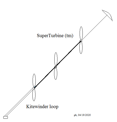
According to the report below, SuperTurbine ™ looks to be efficient (see § 5):
I remake my sketch (see below) because the rope-drive is useless in the SuperTurbine ™ part. The rope-drive connects the lower rotor to the generator at the ground in Kitewinder patent way.
I think the Superturbine tests were done with 25 deg angle. This results in a 25.6% loss in power. For high altitude we have additional wind speed gains. The additional weight can be compensated by a larger lifter kite.
You are right about the rope-drive section. The question remains, how do you orient the turbines to be horizontal if they are connected to the bars? I can think of universal joints and sails (inefficient) or pulleys. Any other ideas?
Variants with universal joints, double universal joints, bevel gears has been discussed.
I think we have to keep it simple. All these variants, comprising pulley system, lead to additional weight and frictions. Certainly there are some (limited for a low angle) losses for SuperTurbine ™ but also some lift, and it is simpler and lighter.
And also an option for multi-rotor on a tether (instead of a bar) can be studied in yo-yo mode.