Here is a video of a system based on Fig. 1a or 5.
As the kite on the video is 2 m² and the wind speed is 5 m/s, assuming a L/D ratio of 4, a rough calculation in pumping (yo-yo) mode would give a mechanical power of about 350 W during reel-out phase, so about 175 W in average, and less in electrical power, but likely more than the given value of 100 W. However said value of 100 W is higher than I expected. And as already mentioned this cannot face all wind directions.
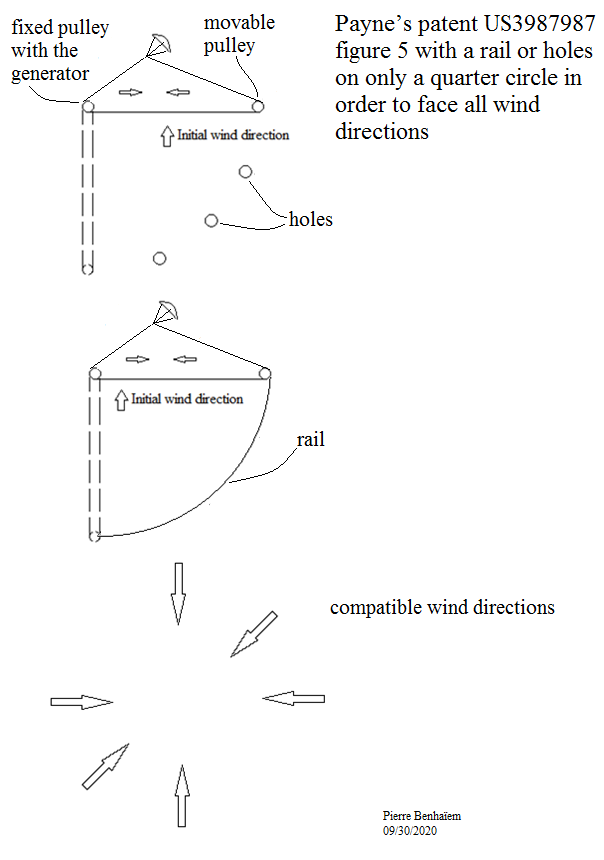
Below is a sketch for a figure 5 system whose the second pulley can move on holes or a rail on only a quarter circle to perfectly adapt to almost all wind directions, and well enough for all.
This is similar in a way to the 3 point anchor, isometric triangle pattern proposed by @kitefreak Dave Santos. Whereby the 2 best suited anchors necessary for Paynes crosswind application would be chosen from the 3 to match to any wind direction within a 60 deg arc
e.g. if you store the operating rig and pulley sets In the space between any 3 of these anchors…
Whichever way the wind is blowing dictates which 2 anchors is the best match for you to deploy and perform side sweep work from
Thank you @Rodread for this drawing that I did not know.
I think my system is far more easy to manage because one (pulley-generator) of the two anchors is always fixed. Only the second anchor (movable pulley) is moving. In the end an automated control could be implemented.
And also a rail on a quarter of circle can save material compared to a complete circle.
TBH can’t remember if Dave ever did mention arraying the system… But he was definitely into the 3 point anchor setups. Arraying it may be something I inferred.
The drawing shows that almost all wind directions are compatible. There is only two gaps that are indicated by the arrows: SE and NW. If we want assume quite all wind directions, we need 180 degrees instead of 90 degrees, but I think it is not essential.
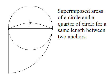
That said the used area (with 90 degrees) is the same as for a complete circle where the two anchors are equally spaced. So the is no area gain. Perhaps the system is easier to manage as the pulley-generator anchor is always fixed.
So as a circle is required for assuming all wind directions for the figure 5 system, using the same circle for a carousel could be more suitable I think.
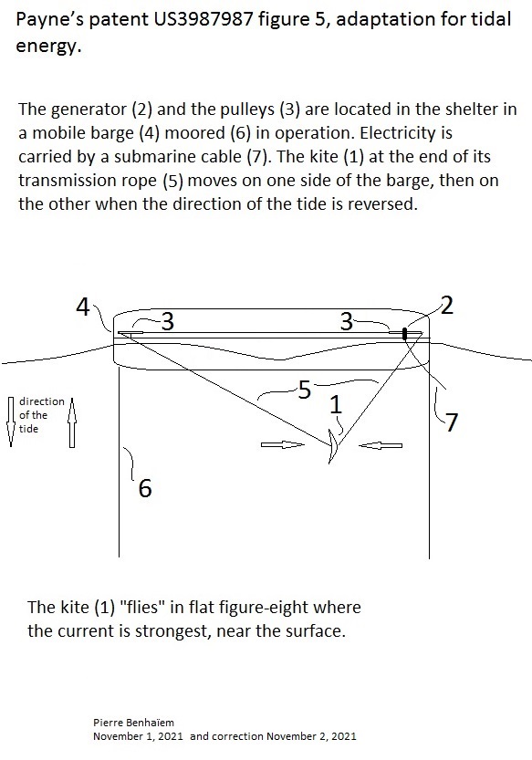
This Payne’s patent US3987987 figure 5 system could perhaps be suitable to harness tidal energy (with a rigid kite like a surfboard, the generator being at the bottom of the water and connected to the submarine cable), since only two opposite directions of flow occur. Possible advantages are a saving in material and the absence of propeller risking hitting the marine fauna. Certainly a reeling yo-yo system could also be used, but by providing a discontinuous power.
An improved version of tidal version of Payne’s figure 5, by using a barge which allows to protect the generator and the pulleys and facilitate maintenance:
Kiteborne (figure 5), Mutiny (25 m², yo-yo mode), SkySails on figure 15 (more than 100 m², yo-yo mode) produce a same average power, all things being equal.
To use @tallakt 's terminology, the device shown in Figure 5 could perhaps belong to the family of “hovering”, while yo-yo mode would enter “bounding”.
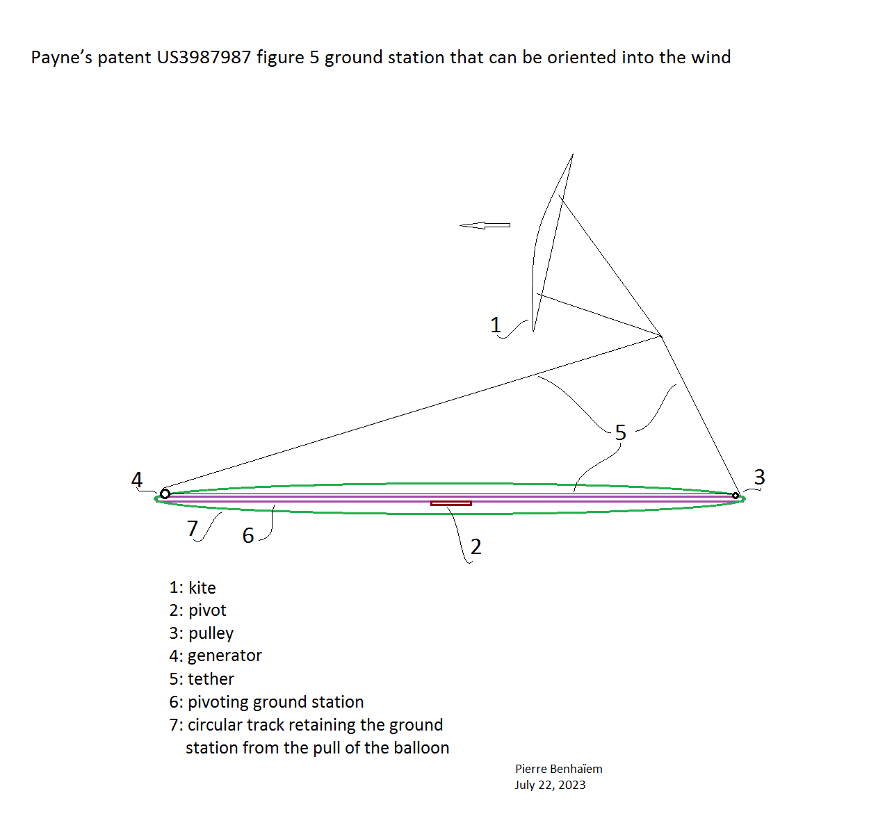
I tried to see what would be the more scalable Magnus Balloon. The ground station can also be used as an adjustable station carrying the generator and the pulley. No rail: the pivoting station is retained by a fixed circular track settled just above.
Thanks for that video, Pierre.
I’m actually pretty impressed. Sure it’s not some huge amount of power, but it is enough to charge a small battery, more than enough to charge a phone, or multiple phones, maybe a tablet or laptop, during, say a camping trip (assuming you have an open field available).
The thing I find significant is it takes one of the early talking points of AWE, and shows it can be easily done. Obviously, it could be built on a somewhat larger scale, for more power. It’s pretty simple, which is good. Pretty quick and easy to deploy, easy to pack up when you’re finished. And of course you could use stakes instead of needing two (2) drill bits.
I tried to verify it by extrapolating with existing data:
(…and wind speed at 6 m height…)
The kite of 2 m² on the video generates an average power of 100 W with 5 m/s wind speed at 2 m at a height of 2 m.
The same average power would be provided by Mutiny by dividing its surface area by 12.5 to get 2 m² (it would no longer be Mutiny), and reducing the wind speed to 5 m/s, if things work in a proportional way, which is not always obvious.