@PierreB In principle what you are talking about can be done like this. I expect this is feasible for enough distance to make sense energy production wise. Launching though can be an issue, because the ground distance required for AWE would be prohibitive.
You can add more pulleys back and forth, but that would add too much friction
@tallakt, Thank you for this rope drive system which takes account of reel-out/in phases, if I understand correctly, and following the discussion about having heavy parts at ground if I remember correctly.
That said, Garrett provides a suitable advice by writing:
In the same time this is indirectly an indication in favor to the efficiency of reeling (yo-yo) systems (working with winches) compared to pulley systems described on What is possible with Payne's patent US3987987 figure 5?.
On reflection, it seems that Garrett has found the right system for a Magnus balloon in reeling mode, with variations in cable length. However:
With a motor on (2) and (2) this could possibly work. Though I expect there could be some losses concerning that the reeling in motor needs to have some force to maintain tether tension on the second (slack) tether, and while in theory that energy is regenerated on the reeling out motor, there would be losses.
Also a brake would be necessary to maintain zero speed efficiently. Otherwise, definitively not impossible. Though I’m not sure if I’m looking at an effective design here. I guess time will tell.
Unless the pulleys, or some of them, were powered and they were only engaged during takeoff and landing. The two outer pulleys would stay static and you’d have a row of pulleys above the rope drive you’ve drawn and one below. To retract the rope drive, the top row of pulleys would move down and the bottom row would move up, giving the rope drive the appearance of laced shoelaces.
The pulleys being powered allows you to add an unlimited number of them.
Or, thinking about it more, you could perhaps do it in 3 dimensions, if you needed to save space:
You’d have the original 2 pulleys, say along the y-axis, the pulleys angled or vertical so that one side of the rope drive is above the other, along this same y-axis a bit to the side of one of side of the loop you’d have a static row of pulleys (with enough space between the pulleys so that the moving pulleys can fit between the static pulleys), to the other side of the loop you’d then have the moving row of pulleys, which then moves along the x-axis to result in this one side of the loop catching on all the pulleys and lots of rows of lines. Next would be to have a static grid of pulleys under or above these rows of lines, and a movable grid of pulleys moving up or down.
That looks like work. But also perhaps a somewhat viable way to extend and retract a rope drive hundreds of meters long, while it was spinning.
Or perhaps instead of this 3d idea you could have, instead of only the one side of the rope drive being engaged by the pulleys, have both sides engaged by pulleys to create two planes above one another, with the pulleys for both planes mounted on the same moving and static arms.
Automatically wrapping and unwrapping the rope drive on and off a drum is probably easier and cheaper. But still probably not very good.
You’d only do this if the rope drive absolutely had to spin all the time. If it only had to start spinning once it was fully extended there are much simpler options.
Hi Garrett, I wonder if higher lift coefficients (CL for a given spin ratio) than those you mention on the poster could be achieved by towing the Magnus kite in a straight line at the same speed as its speed during crosswind flight, so as to avoid all the turns and U-turns that could be detrimental to aerodynamic efficiency and smooth rotation. What are your thoughts on this?
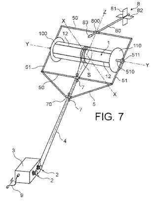
Several interesting points: the motorized winches to turn the rotor are on the ground, and they are also those which ensure the reel-out (power) and reel-in (recovery) phases; the fixed parts of the balloon (the bar carrying the two pairs of pulleys, and the central block maintaining the respective axes of the two balloons) do not undergo the forces which seem to be distributed over the two circular paths for the respective lines around the two respective balloons, limiting the cantilever effects, leaving the way to scalability.
I do not know of a clutch system is needed for the connections of the four winches to the flywheel, and how it would be managed: engaged during power phases, disengaged during recovery phases?
Does the cosine cubed rule, apply to a Magnus Yo-Yo system?
With a Magnus Yo-Yo system, is the optimum power achieved at 1/3 of the wind speed?
Since a lot of the power is lost during retraction, especially at high wind levels, would it not be better to minimize air resistance and retract the balloon so that the end of the balloon is facing the wind up reel?
Relevant questions. Concerning the first two questions, I think that the Magnus yo-yo system behaves like other AWES in yo-yo (first and second questions) or fly-gen mode or even including tilted rotor(s) (first question), in other words all tilted AWES (almost all AWES), with the exception of Kiwee type devices whose the non-tilted propeller does not undergo cosine loss.
The same publication on:
Page 17 (18 on the dispenser): wind speed 10 m/s. Page 18 (19 on the dispenser): the “production phase reel-out speed is 3.3 m/s with an overshoot measured at 8 m/s,[…]”.
For the third question, it would indeed be better, but the maneuver would probably be too complex. You only need to see how the Wind Fisher rotor is held together with the two lines (leading to the four winches on the ground) to understand that this configuration would not allow it.
Just as a Skysails has a nose line, we could attach an extra line to the end of the balloon. During retraction, all four winches should be coordinated with the windup of the extra line so that the lines do not get entangled.
This contradicts the Wind Fisher concept somewhat it seems to me.
Page 3-4:
And this seems to say there is a different cosine rule. I’d say not cosine cubed.
I’d say no. Besides the additional complexity and risk, it takes time to do these maneuvers. Say it takes t seconds to reorient, which you would do 2 times per retraction, taking r seconds, the time spent during optimal orientation would only be r-2t. You don’t know if the retraction phase is even longer than 2t. You don’t know the air resistance during the reorientating phases. You also don’t know if the air resistance in the optimal orientation is so much smaller with the larger diameter of the various disks and the sharp angles between them and the balloons, creating extra drag probably particularly in the proposed orientation.
Making the aerodynamics in the reoriented position better would probably make fabrication more expensive, take away surface area of the balloon during the production phase, and make the unit heavier.
Also, I think control only works if the balloon is in the plane it is now. If you put it in line with the tethers, the tether attachment points, aka their Rope-to-Cylinder Transmission will likely spin around the balloon, tangling the lines. Now the tether tension prevents this from happening, then it won’t I think.
Also, what is the apparent wind direction during retraction that the balloon sees. I don’t think that it is in line with the tethers from the animation, so putting the balloon in line with the tethers wouldn’t be a good idea
This is not what you find in scientific publications, such as those below.
Page 10 and 11 (see also Fig.3):
In analogy to a similar expression in solar power, we might call the loss that is due to the fact that the total aerodynamic force is not perfectly in line with the wind direction the cosine loss.
In fact, all tethered systems need some elevation angle that the tether forms with the horizontal in order to reach some altitude. Fortunately, for moderate angles, the cosine is still close to one, for example the cosine loss is less than 30% even if the tether goes upwards with an angle of 45 degrees. Optimized AWE systems typically fly at even lower elevation angles, and for e.g. 20 degrees we have nearly negligible cosine losses, of only 6%.
The principle is in this excerpt of these sentences: “we might call the loss that is due to the fact that the total aerodynamic force is not perfectly in line with the wind direction the cosine loss.”
See also the equation (45) page 7, which includes the cosine cubed (cos³), below:
This publication is the chapter 12:
Indeed, especially if we consider that two of the authors wrote these two publications including the one I cited last and which relates to crosswind maneuvers.
As you know, to be quick, we take part of the formula to determine the power captured in crosswind flight: Cl (L/D)², Cl being the lift coefficient, L being lift, D being drag.
For a Magnus cylinder, the optimized Cl (with a high spin ratio) is very high, a bit like this. On the other hand the (L/D) ratio is quite low, between approximately 2 and 3, which would give a (L/ D)² between 4 and 9. This is much less than for classic wings. But it is far from negligible. And also the chapter 12 (see Fig. 1.18) and above all the chapter 13, which is available on request, indicate a vertical trajectory far from the winches, and which would be about two times more efficient than the usual oblique trajectory. This vertical trajectory is considered as a crosswind trajectory, although theory (the paper above in the first link of the present comment) indicates that crosswind maneuvers in figure eight are still more efficient than vertical trajectory (about 2 times): this is not expressly indicated but we understand it by cross-checking the information on the two balloons considered in the two respective publications. The problem is that we still have little information (including that from Wind Fisher) on these two crosswind flight modes (vertical trajectory and figure-eight).
My comment was in the context of the quote from the scientific publication I gave. To make it clearer then, I’ll change it to: And this quote seems to say there is a different cosine loss for Magnus based systems. I’d say not cosine cubed like for typical airfoils, but a smaller exponent.
My guess is the projected wing area for a Magnus based system is the same regardless of elevation angle, and that changes the equation.
Do you disagree with my interpretation of the quote or with the quote itself? Or do you think my guess only holds for static kites or for kites that are moving vertically instead of side-to-side?
I think, and this is what emerges from the publications that I cited, that the cosine loss applies for all systems, and depends on the elevation angle: the higher it is, the higher the cosine loss.
This is understandable even intuitively: the wind exerts a force or power on a horizontal vector. The less the AWES is aligned to this force, the more the elevation angle increases, the more the AWES loses by the cosine becoming lower. This does not seem to depend on the aerodynamic characteristics of the AWES, but on its alignment with the wind direction. A typical wind turbine is perfectly aligned to receive wind perpendicular to the rotor disk without cosine loss.
The passage you cited does not seem to call into question this cosine law, but it mentions differences in terms of aerodynamic characteristics.
To return more precisely to the topic, I find that the winch system of Wind Fisher is very ingenious to allow all possible and imaginable maneuvers while ensuring reeling phases. In particular changing the direction of rotation or even stopping it, while the lines are lengthened or shortened, is one of the numerous possibilities.
The patent could also advantageously apply to not crosswind or crosswind vertical trajectory (in addition to crosswind eight-figure such as practiced by Wind Fisher). For a balloon like Omnidea’s, this would allow to avoid rotation motors aloft and the requirement of electric cable from the ground station to the motors. Similar for giant balloons.
For lower performances (and again if this is verified during the tests for vertical trajectory compared to horizontal eight-figure such like practiced) we could additionally have these last two balloons entirely supported by the lines which surround them in several places, without requiring a fixed structure which imposes a rotational movement of the balloon relative to said fixed structure. The patent also covers these configurations.
How high does the MAG fly?
How much space does it take in the sky?
The MAG flies at heights between 200 and 300 m. The flight does not use much space! The MAG flies inside a plane surface. About 500m span. Unlike a kite, the MAG does not go up and down in the air. Just from left to right and back.
All this could lead to a better optimization of the Power to space use ratio. Indeed straight paths, whether vertical or horizontal, are easiest to stack by units flying above or below each other, and side by side, like this (video), in order to harness the whole frontal airspace.
I had wondered how the line could turn the cylindrical balloon without deviating and going out.
As for the prototype, we can clearly see the fixed bar which carries the guides and which makes it possible to restrict the trajectory of the line around the balloon.
So a fixed element is required. The same would apply to all possible variants, whether in yo-yo mode with winches as currently or here, or in rope drive mode as here or there.
This leads me to think that if we can rotate the balloon around said fixed shell with a line, we can also use this same shell (then rotating while the balloon would be fixed) to rotate blades around a balloon or a round kite like here. The question would be whether putting a large annular generator, which would perhaps be lighter, would really be advantageous and reliable. Nothing is certain.
I didn’t see the cosine cubed term in the Diehl chapter. The Magnus paper doesn’t give the derivation of the cosine cubed loss equation and doesn’t explain why it also should apply to rotating cylinders.
A refutation of my point should probably include a reference to either of these papers, just before equation (45), page 7:
Ctrl+F for “cos” in the Loyd paper didn’t give a to me obvious cosine cubed equation. In the Argotov paper equation (69) seems to. I wasn’t able to follow along where the cosine cubed came from.
Earlier in the paper:
Which according to the earlier quote is not the case for Magnus effect-based systems, unless I am reading the above and or below quote wrong.